 TRIZ/USIT
Paper: TRIZ/USIT
Paper: |
  
|
| Experiences
of Teaching and Applying the Essence of TRIZ with Easier USIT Procedure |
Toru Nakagawa
(Osaka
Gakuin University),
Proceedings of TRIZCON2002:
Fourth Annual Altshuller Institute for TRIZ Studies International Conference
held at St.Louis, Missouri, on April 28-30, 2002, pp. |
Discussions
by Ed Sickafus
(NTELLECK, USA) on Nov. 27, 2001 and Dec. 30, 2001.
Slides
prepared for the talk by Toru
Nakagawa on April 21, 2002. |
[Submitted
to the Conference on Nov. 26, 2001 and revised on Jan. 19, 2002.] [Slides
for the talk prepared on April 21, 2002] [Posted here on May 16,
2002]
[Posted in Japanese translation on Jan. 7, 2002.] |
For
going back to Japanese pages, press
buttons.
Preface
(Toru
Nakagawa, May 15, 2002)
This
paper was submitted for presentation and published in the Proceedings of
TRIZCON2002, but was not orally presented in the conference because the
author had to cancell the trip due to some urgent family situation.
The Altshuller Institute has kindly posted this
paper and the slides in their Web site and has allowed me to repost
them in this site.
The paper was
submitted to the Conference on Nov. 26, 2001 in an almost final form.
It describes my expereinces of teaching and applying USIT in 3-day Training
Seminars and the USIT methodology in detail. With this work I myself
was convinced much that USIT has adopted the essence of TRIZ and is an
easy-to-learn and well-structured procedure for creative problem solving.
I sent the
preprint to Dr. Ed Sickafus, the developer of USIT, and on the next day
received his reply via email, saying:
Toru,
great job. I look forward to hearing your presentation. I've
inserted a few comments (mainly for our discussion) and a couple corrections.
All the best, Ed (Nov. 27, 2001)
The discussions
are posted here as well in dark blue fonts, under his permission, for the
sake of readers' better understanding. Section 10.3 was added inDecember.
The paper and discussions were translated into Japanese and posted
in the Japanese page of this site on January 7, 2002.
The slides
were prepared for the talk a week before the conference, and are posted
here in the original PowerPoint file. Please click
here for the slides.
Contents of
the paper are as follows:
Abstract
1.
Introduction
2.
TRIZ/USIT Background in Japan
3.
USIT 3-day Training Seminars
4.
Introduction of USIT
5.
Selecting the Problems to Solve
6.
Problem Definition Stage in USIT
7.
Problem Analysis with Closed-World Method
7.1 Objects, Attributes, and Functions
7.2 Constructing Closed-World Diagram
7.3 Qualitative Change Graphs
7.4 OAF Diagram
7.5 Inplication of the Closed-World Method
8.
Problem Analysis with Particles Method
8.1 Sketches of Present Situation and Ideal Situation
8.2 Action-Property Diagram
9.
Space/Time Characteristics Analysis
10.
Solution Generation Methods
10.1 Operations on Objects, Attributes, and Functions
10.2 Combination and Generalization of Solutions
10.3 Usage of Results of the Analyses in the Solution Generation
Stage
11.
Application of Solution Generation Methods
12.
Usage of TRIZ/USIT in Industries
13.
Evaluation and Current Status of USIT in Japan
Conclusion
Acknowledgement
References
About the
Author
I am very
grateful to:
The Altshuller Institute for TRIZ Studies (USA): Web Site:
http://www.aitriz.org/
Dr. Ed Sickafus, Ntelleck LLC. (USA): Web site:
http://www.u-sit.net/
EXPERIENCES
OF TEACHING AND APPLYING
THE ESSENCE
OF TRIZ WITH EASIER USIT PROCEDURE
TORU NAKAGAWA
ABSTRACT
Experiences of conducting 3-day training seminars
of USIT ("Unified Structured Inventive Thinking") in Japan are reported
in detail. Engineers from multiple companies participated the seminars
and were trained with lectures and group practices of solving real brought-in
problems by applying USIT step by step. Current revised version of
the USIT methodology itself is described in detail, as taught in the 3-day
seminar. Methods of teaching USIT, applying USIT, and introducing
USIT in industries are also described together with the reactions of the
participants.
1.
INTRODUCTION
In order to overcome the present difficulty in
wider penetration of TRIZ ("Theory of Inventive Problem Solving")
[1] into industries, the present author [2]
argued the following points:
-
Presentation of the huge system of knowledge and heuristics
in TRIZ overwhelms the learners.
-
Essence of TRIZ needs to be taught more clearly.
-
Thinking process for creative problem solving needs
to be taught in a simpler way for real application.
-
USIT ("Unified Structured Inventive Thinking") [3]
works well as such a simplified yet powerful procedure for technological
problem solving.
-
Experiences of applying USIT together with TRIZ knowledge
bases have been found effective in industrial applications.
In the present paper, experiences of teaching
USIT and applying USIT to real industrial problems are reported.
Experiences are described below along the course of the present author's
3-Day USIT Training Seminars, where USIT is taught from the beginning and
is applied to real industrial problems brought in by the participants.
2.
TRIZ/USIT BACKGROUND IN JAPAN
TRIZ has been introduced in Japan
[4] for these five years in the forms of monthly journal articles,
textbooks, Web sites (e.g., Nakagawa's "TRIZ Home Page in Japan" [5]),
introductory/training seminars, software tools, etc., almost all in Japanese
language. Thus there are many pioneering engineers in (mostly big)
industries who have been interested in and studying/practicing TRIZ.
Such industrial pioneers had chances of attending TRIZ seminars (of mostly
one to three days) and have already mastered the usage of TRIZ software
tools. However, it has been very difficult for them to master the
TRIZ way of thinking and to obtain the skill of applying TRIZ to their
real problems.
USIT was developed by Ed Sickafus at Ford Motor
Company in 1995 by adapting Israeli SIT, i.e. a simplified version of TRIZ.
He published an intensive textbook of USIT [3]
and two conference papers on his activities [6, 7]
but no compact paper on his methodology. The present author attended
at Sickafus' first out-of-Ford USIT Training Seminar for three days in
March 1999 and started to introduce USIT into Japanese industries.
In 1999 Nakagawa posted three introductory articles
on USIT [8-10] in his Web site, and soon started
to conduct 3-Day USIT Training Seminars [11].
For these nearly three years, he has given many lectures on USIT to TRIZ
users in Japan, posted a large number of USIT-related articles (especially
[12]) in his Web site both in Japanese and in English, and presented
three conference papers [2, 4, 13].
USIT 3-Day Training Seminars have been conducted six times so far, including
3 times under in-company situations [11] and
3 other times under multi-company situations [14].
Thus, most of the participants of his USIT Training Seminars had background
of both TRIZ and USIT beforehand more or less.
3.
USIT 3-DAY TRAINING SEMINARS
The seminars reported here mainly were of multi-company
type, organized by Mitsubishi Research Institute (MRI), and conducted by
the present author as the Instructor. The first seminar of this type
was carried out in January 2000 as reported in detail in
[14], and the second and third ones in July and September, 2001
in a similar but refined way.
From the beginning of sales of TRIZ software tools,
MRI has been organizing users meetings and voluntary study groups of customer
engineers regularly. USIT has been introduced to them in short lectures
and also in a one-day seminar. On such a basis, MRI called for participation
to the 3-Day Training Seminar.
Every participant is requested to bring in a problem
to be solved in the seminar. The problem should be real (or semi-real)
but should not be confidential. This type of request was adapted
from Sickafus' seminar [8] with the intention
to produce experiences of solving real problems with USIT and to enhance
the motivation of the participants.
In order to encourage the participants to bring
in real, worthy-to-solve problems, MRI announced beforehand a Confidentiality
Agreement to be signed by all the parties involved [4,
14]. The Agreement says:
-
The problem proposer and his/her company have the
exclusive commercial rights to use all the findings at the USIT seminar
and to explore the possibilities of filing patents etc. for six months
after the seminar.
-
Other participants (including the Instructor and MRI)
give up claiming any rewards for their contribution, if any, and are forbidden
to report or disclose any technical content of the seminar for six months
even inside his/her company.
-
After six months, any participant (including the Instructor
and MRI) is allowed to report/disclose/publish the technical contents of
the seminar and to explore any further extension concerning the problem.
The policy in this Agreement is based on a
well-known historical Japanese story of Ooka Echizen-no-Kami
[14]. It was established as our solution to the "TRIZ Case-Study
Contradiction":
"For beginners to learn TRIZ, good
examples of successful cases are helpful. But the better the application
results are, the less chances to be published because of companies' secrecy
policies. Thus the beginners do not have chances to study good cases,
and remain as beginners." [14]
The request of bringing in a problem under
the above Confidentiality Agreement actually worked well in cooperative
problem solving in the seminar, but some engineers felt difficulty in the
following points:
-
Difficult to find a real but not confidential problem.
-
As being a staff in a technology management or intellectual-property
rights section, personally have no actual problem to solve,
-
The period of 6 months is too short to explore all
possibilities of resultant new ideas.*A1)
[*A1)
T. Nakagawa, Jan. 7, 2002: In response to this comment, the period
has been changed into one year effective from the Training Seminars to
be held in February 2002.]
The three seminars actually received 12, 9
and 8 participants for the capacity of 15. Most of them were pioneers
of TRIZ and USIT study in their companies, but a quater of them were rather
novices.
Fig. 1 Time Schedule of the 3-Day USIT
Training Seminar
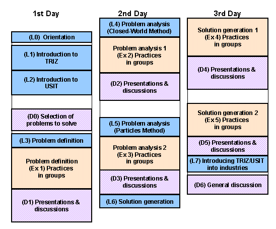
The 3-day seminar was conducted for 24 hours in
total with the time table as shown in Fig. 1.
In the opening of the seminar, the Instructor
shows the target of the seminar as:
"To learn the spirit in TRIZ and to master
the USIT procedure for creative problem-solving and innovation, through
lectures and cooperative group practices of solving real brought-in problems."
The policy of the Confidentiality Agreement
is explained again in the opening and is signed by all the participants
including the Instructor and MRI members.
4.
INTRODUCTION OF USIT
In the morning of the first day, general introduction
is given on TRIZ and then on USIT, so as to learn or remind the basics
of them and to get prepared for the succeeding group practices of solving
real problems with USIT.
The lecture on TRIZ focuses on:
-
New views of technology in TRIZ,
-
Models of problem solving in TRIZ, especially Technical/Physical
Contradictions,
-
Necessity of a simpler problem solving procedure in
TRIZ.
In the introduction of USIT, its historical
background is first summarized with reference to Israeli SIT
[15] and Sickafus' work at Ford [6, 7].
Then, main features of USIT are shown as:
-
Process of problem analysis is well defined.
-
Solution generation techniques are much simplified
and very powerful.
-
Readily applicable to real problems in industries.
-
Does not use knowledge bases (except those in your
brains) and software tools.
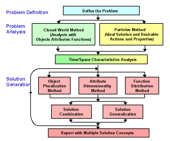
The whole procedure of USIT for creative problem
solving is presented in the flowchart in Fig. 2. This is based on
Sickafus' USIT textbook [3] but is revised
by the present author in several points as the results of his experiences
in Japan, as are mentioned later.
Fig. 2 Flowchart
of the Whole USIT Procedure
The USIT procedure is explained by showing two
full case studies [9, 10] and then step by
step along the procedure together with some other examples, including
[13, 16]. The four principal examples used in the Seminars
are:
-
Detection of small water leakage from a gate valve
[9],
-
Increase the foam ratio in forming a porous polymer
sheet [10],
-
Staircase design of high-rise buildings preparing
against fire [13],
-
Picture hanging kit problem
[16].
5.
SELECTING THE PROBLEMS TO SOLVE
After lunch of the first day, all the participants
are invited to introduce themselves and their brought-in problems one after
another for about 5 minutes each. The problems are submitted beforehand
to the organizer in one-page free format of A4 size, containing brief explanation
and some illustrative figure(s). People are advised to explain not
only the difficulty of the problem itself but also its significance, its
rough mechanism, his/her technical background and career, etc.
Then we start the session for selecting the problems
to solve together in the Seminar. The Instructor explains the present
situation as:
-
We are going to solve 3 (or 4) problems in this Seminar
in parallel.
-
For each problem we want to have a group of 3 to 5
members.
-
Thus we need to select the problems which we actually
tackle.
The number of problems to be solved is determined
by the time available especially at the sequential presentation/discussion
and by our capacity of understanding all the problems at the same time.
Less number of problems (i.e., 2 or 1) is not desirable because the participants
cannot see different enough aspects and situations in applying USIT.
For selecting the problems, the Instructor advises
the following criteria:
-
Significance of the problem (i.e., expectation of
large merit or profit once it is solved),
-
Clearness in the problem definition (i.e., not vague,
not open-ended, not too large),
-
The proposer of the problem has sufficient technological
knowledge of the problem and enthusiasm for solving it.
-
At least one or two other participants have some general
background in the field of the problem.
-
Apparent easiness of the problem is NOT necessary
at all.
-
If the proposer already has a solution idea strongly
in his mind but cannot disclose it because of its confidency, it would
rather become a barrier for group practice.*1)
[*1)
E. Sickafus, Nov. 27, 2001: I deal with prior knowledge by
having the students stand before the class and list all known solutions
to his/her problem. During this exercise considerable brainstorming
occurs and we list these solutions also. This procedure clears the
table (so to speak) and sets the stage for USIT to be better appreciated
for its efficiency and thoroughness.]
Then the Instructor asks the participants to
raise their hands if he/she eagerly wants to tackle his/her own problem
at the Seminar. Some of the participants may not raise their hands,
possibly because they are not personally involved in their brought-in problems
or because they feel their problems too broad/vague.
Then we usually select the problems by voting.
Every participant is given two votes for the problems (other than his/her
own) which he/she wants to join to solve. This voting usually (i.e.,
in all the three cases of our experience) makes a reasonable result.
It is nice that not the Instructor but the whole participants have decided
the problems to tackle in a fair and open manner.
Finally, participants are assigned to groups for
selected problems, on the basis of their votes. Proposers of the
selected problems belong to the group of their own, of course. Since
other participants stated two choices in the voting, it is usually not
difficult to make such practice groups. It is desirable to form groups
with members having different backgrounds and specialties. Multiple
participants from a company are advised to join different groups.
Now that the problems and group members are decided,
we start the group practices of solving the problems by use of the USIT
procedure in five sessions for two days and half. Each session has
the following three sub-sessions (as adopted from Sickafus' Seminar [8]):
-
Lecture of the process to be applied in the session
(for 40 - 60 minutes),
-
Group practices in parallel (for about 2 hours) using
electronically-recordable whiteboards (meanwhile the Instructor joins/watches
the groups by turn and advises from time to time),
-
Sequential presentations by the groups to all the
members, along with discussions and instructions (for 20 - 30 minutes for
each group).
6.
PROBLEM DEFINITION STAGE IN USIT
In this stage, the proposer explains the problem
again in more detail to the group members, and the group makes Q&A
and discussions and finally writes down the following items in a concise
manner:
-
Problem Statement: Define
the problem well in one or two lines.
-
Sketch: A simple conceptual
drawing of the problem situation so as to clarify its mechanism
-
List of Objects: Objects
needed to understand the problem.
-
Plausible Root Causes:
One or multiple causes written in brief statements.
In the lecture of this session, the Instructor
emphasizes the following points:
-
The problem should be considered in a hierarchical
system of problems, both in wider and in more specific scopes (see e.g.,
[13]).
-
Setting a problem is equivalent to setting a goal;
thus, set it as meaningful as possible.
-
The main purpose of this stage is to decide the focus
of the problem. If the proposed problem contains a few related problems,
separate them and choose one of them.
-
Clarify the focus of the problem and state it in the
well-defined form (i.e. a problem specified by the above-mentioned set
of requirements).
In relation to the Plausible Root Causes, the
following points are remarked:
-
For finding Plausible Root Causes, consider the (physical)
mechanism of the present system and its problem. If not clear enough,
try to find them in each of the objects in the system.
-
The effect-cause relationships form a sequence and
may be extended deeper but become more unclear; thus you have to be satisfied
by setting your root causes at the level you can handle. Such root
causes are the focal points to solve.
-
Here you think your root causes as plausible ones,
but you have to check them by experiments (beforehand or afterwards).
This Problem Definition Stage appears to be
simple and easy to conduct at first sight. However, at the end of
the Seminar, most of the participants say that this is the step found most
crucial and hence difficult in the whole problem solving procedure.
Concise statements of problem definition and Plausible Root Causes clearly
determine the direction of all the subsequent efforts for solving the problem.
The one-page problem statements submitted beforehand
by the proposers have more detailed descriptions but often found unclear
and less significant under the requirements in USIT. The capability
of the proposer to adapt the group discussion flexibly is found to be the
key to fruitful/productive results in the seminar.
In a case conducted in [14],
the problem proposal was "to find a method of discriminating micro-bubbles
from small contaminants at the monitoring station in the loop of washing
liquid for cleaning the wafers of micro-electronic devices". The
group found "the methods to eliminate or to avoid producing micro-bubbles"
were more significant as the problem definition. Even though the
proposer was in charge of monitoring the washing liquid, he was flexible
to shift the focus of the problem; thus his group succeeded in making meaningful
and productive solutions as the results of the Seminar.
In another case conducted in
[14], the proposer wanted to "find a method of breaking waste plastic
cases of TV sets, vacuum cleaners, etc. in relatively larger pieces".
The waste plastic cases need to be broken at the site of collection for
easier transportation to the processing site, where the plastic pieces
are classified according to their materials after analysis. The analyzer
is large and not portable. If the plastic cases are crushed in ordinary
ways such as pressing, many small pieces are produced and decrease the
efficiency of the analysis and classification. Though the group members
asked and suggested about possibilities of other processing orders, the
proposer insisted that this processing order is his definite conclusion
after a large number of trials. So the group followed the proposal
and made hard efforts for breaking plastics into larger pieces without
producing smaller ones.
Just before lunch time of the third day, a group
member came up with a simple idea of "putting all crushed pieces
from a wasted case into a separate bag." Only a piece in a bag need
to be analyzed for classifying the bag. This idea was outside the
problem definition but solved the problem quite efficiently. This
example shows the importance of considering the whole process (or the whole
problem system) in more flexible eyes at the stage of Problem Definition.
[*2)
E. Sickafus, Nov. 27, 2001: In the problem definition stage (before
analysis) do you reduce a problem to its minimum number of objects?
Do you discuss points of contact and active attributes in order to force
students to think about fundamental phenomena supporting the functions
of the system? ]
7.
PROBLEM ANALYSIS WITH CLOSED-WORLD METHOD
In the morning of the second day we start the Problem
Analysis Stage in USIT. As shown in the flowchart in Fig. 2, USIT
has three analysis methods:
-
Closed-World Method: To analyze the problem
by starting with the present system.
-
Particles Method: To analyze the problem starting
with an image of ideal solution first.
-
Space/Time Characteristic Analysis: To find
"uniqueness" or characteristic properties in space and in time.
In USIT either one or both of Closed-World
Method and Particles Method may be used, depending on the nature of the
problem. In the present author's Training Seminar, these two methods
are applied sequentially in this order to all the problems, for the purpose
of understanding their effectiveness and contributions. The Space/Time
Characteristic Analysis should be carried out always.
At the beginning of the Problem Analysis Stage,
we first introduce USIT's basic concepts of Objects, Attributes, and Functions,
and then start to analyze with the Closed World Method.
7.1 Objects, Attributes,
and Functions
Most important contribution of USIT to the problem
solving methodology is its introduction of the basic concepts of Objects,
Attributes, and Functions and its utilization of them in a unified way
throughout the whole procedure. They are defined as
[3, 17]:
-
Objects: Exist of themselves, occupy space,
and interact with other objects to modify (or else prevent from modifying)
their attributes.
-
Attributes: Are characteristics (but not metrics
or values) of Objects.
-
Functions: Cause (or else prevent from) modification
of Attributes of Objects.
It is very instructive to show Sickafus' examples
and anti-examples of these concepts [3, 17].
-
Objects: A nail, an airplane, an electron, light
(a photon), air, "information", ...
-
Non-objects: A hole, force, heat, electric current,
... (because these do not exist of themselves)
-
Attributes: Color, weight, shape, position,
refractive index, ... (these are expressed in categories)
-
Non-attributes: Red, 10 kg, square, ... (because
these are metrics, i.e. values of Attributes)
-
Functions: To accelerate, to give force, to
change color, to contain, ...
It is important to notice that these concepts
are interrelated. Sickafus shows the scheme:
"A Function interacts an Attribute of
an Object with an Attribute of another (or the same) Object to modify (or
else prevent from modifying) an Attribute of a third (or the same) Object".
His point is that among various Attributes
of interacting Objects we may always select one most significant Attribute
for each Object in the above scheme. For instance, he expresses the
bolt-nut Function as:
"The Angle of the Bolt interacts with
the Pitch of the Nut to change the Position of the Bolt".*3)
[*3)
E. Sickafus, Nov. 27, 2001: At a point of contact between two objects
there can be multiple pairs of attributes support the same or different
functions. Insights are gained by identifying as many of these as
seem cogent.]
Sickafus' definition of Objects, Attributes,
and Functions is rather strict and may not be easy to follow at first for
a learner, but later it becomes clear to understand and quite agreeable
more and more.
"Information" is regarded as a kind of Object in
USIT so as to explain wide variety of problems for detection, measurement,
control, etc. in a simpler and consistent way (see, e.g.,
[9]).
7.2 Constructing
Closed-World Diagram
In the Closed-World Method, we should first construct
the Closed-World Diagram. This is the USIT way of functional analysis
for clarifying the functional relationships among the Minimal Set of Objects
in the original design intention of the present system.
The Minimum Set of Objects are a set of Objects
absolutely needed to contain the problem and are extracted from the Objects
listed up in the Problem Definition Stage. In the process of choosing
the Minimal Set of Objects, the names of the Objects should be made generic
in order to avoid Psychological Inertia by technical terms. Note
that this step has been moved in this paper from its original position
in the Problem Definition Stage.*4)
[*4)
E. Sickafus, Nov. 27, 2001: This answers my question about minimal set
of objects.]
Sickafus sets the following rules for constructing
the Closed-World Diagram:
-
Find the most important Object A in the system and
place it at the top of the Diagram.
-
Then arrange other Objects downward in the order "functionally
beneficial to the upper Object" (see below for detail) and draw an upward
arrow with the name of the beneficial Function.
-
Arrange all the Objects in the Minimal Set of Objects
without duplicating or neglecting.
-
If there is any Object not in the "functionally beneficial
relationship" to others, place it aside as redundant or in a side diagram.
The "functionally beneficial" relationship
of Object B toward Object A means simultaneously that:
-
B has a beneficial Function which supports A: e.g.,
B generates A; B modifies an Attribute of A; B eliminates A; etc.
-
B has a direct physical contact to A and performs
the functional interaction.
-
In the design intention of the system, A has come
prior to B; A is B's reason for existence; thus, if A is eliminated, B
becomes redundant.
These rules are rather strict and urge the
analysts to draw quite simple diagrams showing the Objects and their principal
(i.e. beneficial) Functions, for the purpose of revealing the intention
of the original design of the present system. Once such a simple
diagram is drawn, it conveys much clearer message than ordinary functional-analysis
diagrams which show a large number of arrows of less significant functions
as well.
However, even though a number of examples of Closed-World
Diagrams are shown in Sickafus' textbook [3],
his Seminar Materials [17], and in my Web
site [2, 9, 16], they are not sufficient yet
for USIT learners to master this diagram. In our USIT Seminars in
Japan, we have been learning Sickafus' real intention little by little,
through the experiences of various cases.
The present author sometimes felt temptations to
additionally draw harmful/insufficient functions, subsidiary functions,
points of problem, etc. in this diagram.*5)
But he now understands that the simple drawing structure should not be
distorted or changed and that under such restriction it is not harmful
to put some additional description when it helps to make the problem clearer.
Sickafus says that the Closed-World Diagram analyzes not the problem but
the system as it was designed to function properly.*6)
[*5)
E. Sickafus, Nov. 27, 2001: This is a common tendency for newcomers
to USIT. I think it arises from good technical training to do complete
detailed analyses. Whereas, USIT is about creating new viewpoints
of a problem quickly. USIT is intentionally designed to avoid the
typical engineering analysis. The reason is that the value of USIT
is to offer new ways to look at a problem. We already know how to
do engineering.]
[*6)
E. Sickafus, Nov. 27, 2001: I believe it is helpful to point out
to students that the CW-diagram does not analyze the problem. Instead,
it analyses the system as it was designed to function properly.]
7.3 Qualitative
Change Graphs
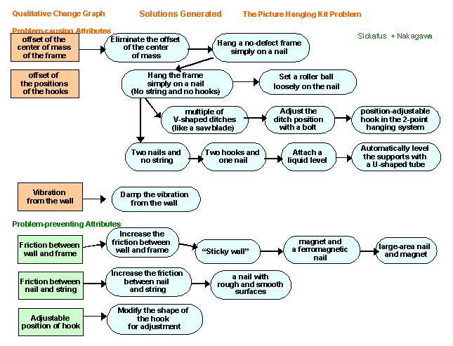
We next analyze the harmful/insufficient effects
in the problem in terms of Attributes of Objects. This analysis complements
the preceding analysis with the Closed-World Diagram.
Fig. 3 Qualitative Change Graphs.
Picture Hanging Kit Problem [17]
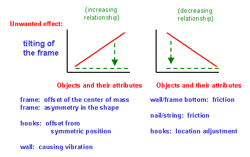
The Qualitative Change Graphs are actually the
two prefixed graphs, as illustrated in Fig. 3, in which we are requested
to specify the ordinates and the abscissa as:
-
Ordinate: The principal harmful/insufficient
effect in the problem; the same effect must be chosen in the two graphs.
-
Abscissa: Two lists of the Attributes of Objects
which have increasing and decreasing relationships, respectively, to the
effect shown in the ordinate.
We should understand that these graphs are
schematic just to show increasing/decreasing relations in multiple graphs
without distinguishing their actual details.
The left graph simply says that if one of the Attributes
in the list increases, then the harmful/insufficient effect of the problem
increases. Thus we may regard these Attributes as "problem-causing
Attributes". On the other hand, if any Attribute shown under the
right graph increases, the harmful/insufficient effect will decrease.
Thus we may call such Attributes as "problem-preventing Attributes".*A2)
[*A2)
E. Sickafus, Dec. 30, 2001: This is a bit confusing. "Problem-causing
attributes" are the inverse of "problem-preventing attributes". They
are not different attributes.]
The present explanation is simpler and more
effective than the one in Sickafus' Seminar in 1999
[9]. Now, it is not necessary to list up as many Attributes
as possible for all the Objects at the stage of Closed-World Diagram and
to eliminate irrelevant Attributes in this stage of Qualitative Change
Graphs.*7)
[*7)
E. Sickafus, Nov. 27, 2001: I would argue that all attributes identified
in the palusible root-causes analysis belong in the QC-diagrams.
Furthermore, each attribute offers a point of focus for finding solution
concepts.]
7.4 OAF Diagram
Next in the Closed-World Method, Sickafus uses
Object-Attribute-Function (OAF) Statements and OAF Diagram in his textbook
[3]
and in the recent examples posted in his Web site [18].
They request explicit and consistent statements of all relevant Functions
in terms of Attributes, in the form mentioned in Section 7.1.
Sickafus did not teach the OAF Diagram in his 3-day
Seminar in 1999 [8] because of shortage in
time. The present author feels this method too complicated, and has
decided not to teach/use it in Japan.*8) *9)
*A3)
[*8)
E. Sickafus, Nov. 27, 2001: Where I find the OAF diagram most useful
is as an aid to understanding and identifying attributes. Most students
being introduced to USIT have little trouble understanding objects (except
for information) and quickly learn to understand functions. However,
many have difficulty with attributes, especially when asked to use them
as a point of focus in applying dimensionality as a solution technique.
That learning to identify and use attributes may be difficult should not
be considered to be a drawback of the methodology. It is not if the
result of learning attributes strengthens ones abilities as a problem
solver. OAF diagrams are a tool for this purpose.]
[*9)
T. Nakagawa, Dec. 28, 2001: The present author feel that the participants
of his USIT Seminars in Japan do not feel so much difficulty in understanding
the concepts of attributes. In the early stage of USIT lecture, the
case study of "Detection of small water leakage from a gate valve" is usually
presented. In this case, various properties of water are shown in
terms of Attributes, and they are intensively used in finding various solutions
by use of the Attribute Dimensionality Method. This may be a reason
why Japanese USIT learners understand the use of the Attributes relatively
smoothly.
In order to
teach the OAF Diagram at the Training Seminar, it would take 1.5 to 2 hours
additionally for lecturing and practicing at a level to make the OAF Diagrams
in a somewhat consistent way. Yet, the present author is afraid that
the participants do not really feel themselves confident in their understanding
of correct way of constructing the OAF Diagram and in its usefulness.
At the present situation, without the OAF Diagram, we do not feel such
needs of it. The present author believe that it is a nice policy
for us to keep USIT concisely at the level where its whole theory and practices
can be learned in three days at the Training Seminar and the seminar participants
can be convinced of the usefulness of every step of the USIT procedure.
So the present author would choose not to teach OAF Diagrams at his USIT
courses. ]
[*A3)
E. Sickafus, Dec. 30, 2001: I don't use OAF diagrams unless needed.
I pay attention to students comments and questions in class to try and
detect any uncertainity on their part regarding the meaning of attributes.
If I find students confusing attributes and metrics, as an example, this
is an indicator to me that they may benefit from OAF diagrams. The
most obvious difficulties surface when teams begin to report their solution
concepts to real-world problems they solve in class. The instructor
quickly becomes aware of any imbalance between the metaphorical strength
of objects, attributes, and functions in leading a team to new solution
concepts. Such imbalance, when it exists, is a clue to areas that
may need new emphasis by the instructor. ]
7.5 Implication of
the Closed-World Method
Real significance of the Closed-World Method can
best be understood in reference to Roni Horowitz' papers and ASIT
[15, 19].
Roni Horowitz and Oded Maimon [15]
demonstrated by experiments that engineering people agree to regard a solution
as "inventive" if it satisfies the following two conditions:
-
Closed-World Restriction: The solution does
not introduce any new Object of type different from the ones in the Closed-World
(Diagram). It may introduce Objects of the same type with modified
properties.
-
Qualitative Change Requirement: According to
the solution, the increasing/decreasing relationship of an Attribute has
changed qualitatively so that the harmful/insufficient effect can be eliminated.
The Closed-World Restriction may be understood
as a form of TRIZ' concepts of minimal introduction of Resources and of
Ideality.
The Qualitative Change Requirement can be explained
in the following way:
When we learn a problem causing relationship as
shown in the left graph, we would immediately think of a method, i.e.
-
To reduce the value of the problem-causing Attribute,
so as to decrease the harmful effect along the existing slope.
This will results in an ordinary engineering solution
(in case of easy problems) or in some situation in Technical Contradiction
(in case of difficult problems).
"Inventive solutions", on the other hand, are the
cases where any of the following three types of Qualitative Change is achieved:
-
To make the problem-causing Attribute actually inapplicable.
-
To convert the increasing relationship for the problem-causing
Attribute into a non-increasing relationship.
-
To turn the harmful effect into a useful effect.
It should be remarked that these three ways
of thinking are more straightforward than the TRIZ way of thinking, i.e.
constructing the Technical Contradictions and then searching for possible
ways to solve them.
ASIT ("Advanced Structured Inventive Thinking")
[15] has the policy to concentrate their problem-solving efforts
to the search for "Inventive solutions" satisfying the above-mentioned
two conditions. This may be a "purified" TRIZ approach. Examples
of such solutions may be found in the Web site of Horowitz
[20].
However, USIT's approach is different from ASIT.
Sickafus wrote in [7] that he decided to put
stress not on the search for "Inventive solutions" but on quickly obtaining
multiple creative solutions to real industrial problems. He has chosen
this policy in order to maximize the merit of creative problem solving
in real industrial situations like at Ford.
Thus, in USIT, even while we understand the ASIT
approach, we rather use the Closed-World Diagram as a method of functional
analysis, and the Qualitative Change Graphs as a method for analyzing the
problem-causing and problem-preventing Attributes. These diagram/graphs
are referred later in the Solution Generation Stage (See Section 11).*10)
[*10)
E. Sickafus, Nov. 27, 2001: A philosophical note: TRIZ emphasizes
the identification of contradiction among pairs of effects. This
is often a troublesome step for students. Once a contradiction is
found, the next step is to separate its parts. USIT takes the approach
of ignoring contradictions and identifying all plausible root causes.
Each is treated individually. This procedure leaps over the TRIZ
step of finding contradictions. ]
8.
PROBLEM ANALYSIS WITH PARTICLES METHOD
Particles Method was adopted from Altshuller's
Smart Little People's Modeling [1] but was
extended and refined much by Sickafus [3].
This method is the approach to think of an image of the "Ideal Solution"
first and hence is applicable even to the cases where we do not have any
present system yet.
As application examples of this Particles Method,
the present author has always used, in his USIT Training Seminars [11,
14] as well as in his papers [2, 4, 12],
the case of "Increase the Foam Ratio in Forming a Porous Polymer Sheet"
[10].
The case was made at Sickafus' Training Seminar [8]
as a trainee. This one example has been very useful in teaching the
Particles Method. Almost all trainees in the 3-Day Training Seminars
applied the method well to their problems and found it easy and powerful.
(Please refer the figures of this case in previous publications mentioned
above.)
8.1 Sketches of
Present Situation and Ideal Situation
First we draw a sketch of the present situation
to clarify the mechanism of the harmful/ insufficient effect of the problem.
This is often a close-up view of the sketch we drew in the Problem Definition
Stage, and corresponds to the view in the Operational Space in TRIZ.
Then we are requested to draw a sketch of the Ideal
Situation. We should draw the situation itself without thinking/drawing
any means to achieve it. This request often sounds very difficult
at first and gives us a shock to change ourselves in our thinking ways.
Then we somehow squeeze out a sketch of an ideal situation, even though
it appears absurd at first. Inserting a few key words in the sketch
is helpful to clarify the situation.
And then we are requested to compare the two sketches
and put small "x marks" at the places wherever we see any difference.
We should not restrict ourselves in choosing these places on the basis
of our guess of solutions.
These "x marks" are now called the "Particles".
Particles are supposed to be magical substances/Fields which can perform
any desirable actions and can have any desirable properties. Then,
we are asked what sort of actions we want them to perform and what sort
of properties we want them to have.
8.2 Action-Property
Diagram
We now write the action we want the Particles to
perform in one sentence. This is easily done by taking the keywords
in our sketch of Ideal Situation and by converting them into a sentence.
Since the sentence often includes a few action keywords combined with "and",
such actions are then described separately at the second level with explicit
indication of the AND relationships. Then each action should be broken
down further into possible elements of actions and drawn in a form of the
AND/OR Tree known in logic.*11)
[*11)
E. Sickafus, Nov. 27, 2001: Maybe we are saying the same things,
but I put a little different emphasis on the process. I start by
having the students write a statement of the ideal solution as a compound
sentence without concern for the particles. Then the sentence, in
the next lower level, is divided into its and/or clauses. In the
next lower level the student now considers what the particles are doing
to accomplish the actions of the particles. Under actions are listed
multiple properties that support the actions. ]
The Instructor advises as follows:
-
Use plain words, in place of technical terms, in order
to avoid Psychological Inertia and to stimulate ideas of wider types of
actions.
-
Think of actions as widely as possible and combine
alternative ideas of actions with the OR relationship.
-
Break down an action element independently of neighboring
ones.
-
Stop at third or fourth level.
Next we should list up possible desirable properties
for performing these actions. The guide lines are:
-
Think of possible desirable properties for performing
each bottom-level action, and list them up at the bottom of the Action-Property
Diagram.
-
Write down any idea of desirable property without
trying to evaluate its feasibility at this step.
-
Enhance and remember any idea of possible implementation
of such desirable properties.
In the Training Seminars, the groups are very
often excited in this session to find themselves coming up with a variety
of new ideas in combination of actions and properties.
9.
SPACE/TIME CHARACTERISTICS ANALYSIS
At the final step in the Problem Analysis Stage
in USIT, the problem is analyzed to clarify its Space and Time Characteristics
(or "Uniqueness" in Sickafus' preferring term [3]).
The Space Characteristic Analysis usually draw
a graph in the following way:
-
Choose, as the ordinate, either a performance index
of the principal function or an index of the harmful/insufficient effect.
-
Choose, as the abscissa, some spatial axis (or route)
suitable for representing the problem's characteristic and its unique behavior.
This may be curved, non-linear in scale, and qualitative.
-
Draw the characteristics of the problem in this graph
qualitatively.
-
Draw the characteristics of the Ideal Situation in
the same graph.
The Time Characteristics Analysis is also done
in a similar way by drawing a graph with some suitably-chosen time axis.
Examples of these graphs can be seen in
[9, 10, 12, 16]. The choice of characteristic spatial/temporal
axes is the key to the expressive power of these graphs. In the case
of the "Micro-bubbles in washing liquid" problem, the looped route of the
circulating washing liquid was chosen as the spatial 'axis', and the whole
process cycle of washing the wafers was taken as the temporal 'axis'.
This analysis method can be used flexibly.
Sometimes drawings of system's structure itself (see
[16]) and block diagrams of a complicated system serve to show their
spatial characteristics.
Doing the process analysis at this step should
have a wide application area. For example, in the case of the problem
of "Breaking waste plastic cases", mentioned in Section 6, we should have
done the process analysis in more detail in this step.
Once such spatial/temporal axes chosen properly,
the graphs suggest important viewpoints for understanding the unique nature
of the problem, and further give hints of interesting ideas similar to
those obtainable with the Separation Principle in TRIZ.
Originally, Sickafus [3]
placed this method as a connecting link in between the Problem Analysis
and Solution Generation Stages, because this method, though an analysis
in nature, often stimulates solution ideas. The present author, however,
places this method at the final step in the Problem Analysis Stage [8],
as shown in the flowchart in Fig. 2. It is clear that this analysis
should be done only once before the repeating processes in the Solution
Generation Stage.*12)
[*12)
E. Sickafus, Nov. 27, 2001: I introduce Uniqueness at the end of
analysis and the beginning of solution techniques but emphasize it as a
solution technique, as you know. My reasoning is that the graphic
display of desired functions as rectangles in space/time lead immediately
and intuitively to solution by separation, overlapping, reversing, division,
multiplexing, and demultiplexing. This makes the subsequent solution techniques
much more easily understood. ]
10.
SOLUTION GENERATION METHODS
We now start the third stage in USIT, i.e. Solution
Generation Stage. As shown in the flowchart in Fig. 2, we use five
Solution Generation Methods (or Operators) repeatedly to generate multiple
conceptual solutions.
The five methods are grouped into two categories:
Three methods are to be applied on Objects, Attributes, and Functions,
respectively, whereas the other two methods are to be applied on Concepts
(or Solutions).
10.1 Operations
on Objects, Attributes, and Functions
Corresponding to the basic concepts of "Objects,
Attributes, and Functions" for representing any technical system, USIT
provides three Solution Generation Methods:
-
Object Pluralization Method,
-
Attribute Dimensionality Method, and
-
Function Distribution Method.
Note that Sickafus [3, 18]
calls these simply as Pluralization, Dimensionality, and Distribution.
The Object Pluralization Method is applied to (or
operated on) every Object in the system (especially those in the Minimal
Set of Objects) so as to "Pluralize" it. This operation has the following
aspects:
-
Trim the Object (i.e., reduce into 0), and then try
to find any solution by using the simplified system.
-
Multiply the Object (i.e., 2 times, 3 times, ... and
infinite times), and then think of using them with some modification in
their properties.
-
Divide the Object (i.e., into halves, into thirds,
... and into infinitely small parts), and then think of integrating them
after some modification.
The Attribute Dimensionality Method is applied
to (or operated on) various Attributes of every Object in the system so
as to modify the "Dimensionality" of the Object. This operation contains
the following aspects:
-
De-activate the Attribute (especially the existing
harmful one) (i.e., do not use it or make it not involved).
-
Activate an Attribute (especially a new useful one)
(i.e., start to use it or get it involved).
-
Vary the Attribute (especially either problem-causing
or problem-preventing one) in space and/or in time (i.e., make it different
in space and/or in time, or make it constant in space and/or in time).
-
Convert the space- and time-dependencies of the Attribute.
The Function Distribution Method is applied
to (or operated on) all the Functions in the system so as to "Distribute"
(or re-arrange) the functions among the Objects in the system (including
newly introduced Objects). The guidelines are:
-
Assign the Function to a different Object (either
existing or newly introduced Object).
-
Unify two Functions supported by two Objects, so as
to let the unified Function be supported by one Object and eliminate the
other Object if it becomes redundant.
-
Divide the Function and assign the divided Functions
to multiple Objects separated either in space or in time.
-
Introduce a new Function.
Examples of application of these three Solution
Generation Methods can be seen in Sickafus' textbook
[3], his recent application example [18],
and in Nakagawa's articles [9, 16].
Examples by Horowitz [21] in the ASIT method
are also helpful.
Readers familiar with TRIZ [1]
may understand that various methods in 40 Principles of Invention can be
shuffled into the above three Solution Generation Methods and that the
knowledge of Trends of Evolution may be actively used in these methods.
Thus these USIT methods are not a small selection of TRIZ (or any other)
methods but rather a full set of TRIZ methods expressed in a way simple
and easy to apply.
It has been traditional [1,
3] to show solutions as the result of application of either one
of the solution-generation methods. However, such solutions can be
viewed in multiple ways as results of different USIT Solution Generation
Methods. Three methods in USIT focus their operations on either one
of the three aspects (i.e., Objects, Attributes, and Functions), yet they
usually generate some side effects on other aspects, as you see in the
description of the methods. This is inevitable because none of the
three aspects can exist by itself. Thus, we should understand that
any solution can be regarded in multiple ways as the application results
of different USIT Solution Generation Methods [16].
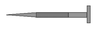
Figure 4 demonstrates such a solution in case of
"Picture Hanging Kit Problem" [16].
As a solution for preventing a picture frame from tilting, the nail on
the wall is made partly rough and partly smooth on its surface
[3]. The hanging string should be adjusted at the smooth surface
of the nail and then set at the rough surface.
Fig. 4. A nail with smooth and rough surfaces
(by Ed Sickafus [3])
This single solution can be viewed in the following
four ways simultaneously [16]:
-
The Nail Object was doubled (or divided into halves)
and then combined (by Object Pluralization Method).
-
The Smoothness Attribute of the Nail Object was made
different in space on the nail (by Attribute Dimensionality Method).
-
The Adjusting Function and the Holding Function of
the Nail Object were separated and assigned to different parts of the Nail
Object (by Function Distribution Method).
-
The Nail surface must be smooth for adjusting and
rough for stable holding; hence, the opposite requirements were separated
in space and then combined (by TRIZ Separation Principle, and also by USIT
Solution Combination Method).
This understanding of solutions in multiple
ways made the present author much easier to teach and apply these Solution
Generation Methods.
10.2 Combination
and Generalization of Solutions
The last two Solution Generation Methods are different
from the former three at the point that they operate not on the elements
of the system but on the solutions.
The (Solution) Combination Method is applied to
multiple solutions (or solution elements) and combines them in various
ways in space, in time, in parts, etc. to form a new solution.
Originally in USIT, Sickafus
[3] defines a method named "Transduction". It forms a sequential
link between two Functions with a common Attribute of an Object as the
bridge. This means the two Functions are performed in coordination
simultaneously, in sequence in space or in time, etc. The present
(Solution) Combination Method [16] is an extension
of Sickafus' Transduction and covers much wider area of solution generation
methods.
The (Solution) Combination Method has the following
guide lines:
-
Combine two solutions in a functional way, so as to
enhance/extend/prevent one of the functions.
-
Combine multiple solutions in time, so as to perform
the solutions in sequence (one after the other), beforehand, afterwards,
by turn, in cycle, in the reverse order, etc.
-
Combine multiple solutions in space, so as to perform
the solutions independently at different places, side by side, in sequence
in the space, on top of the other, inside of the other, alternatively at
the same place, etc.
-
Combine multiple solutions in structure, so as to
perform the solutions in different levels, under different conditions,
etc.
-
Combine multiple solutions in spirit, so as to perform
the solutions in hybrid, in compromise, in background of the other, etc.
It is clear that the (Solution) Combination
Method naturally contains a wide range of solution methods, such as those
included in 40 Principles of Invention. Especially, the Separation
Principle in TRIZ [1] may be regarded essentially
the same, but expressed in the opposite way, with the (Solution) Combination
Method. Whereas the Separation Principle says "to separate a contradiction,
and then to combine", the present method simply says "to combine" in a
way much easier to understand. Thus, even though some of the solutions
generated with the Combination Method may also be interpreted as the results
of other three Solution Generation Methods (just as shown in Fig. 4), this
method has a unique and important position in the whole theory of USIT,
as shown in Fig. 2.
The (Solution) Generalization Method encourages
to replace technical, specific terms in each solution with plain, generic
terms [3]. This makes the solutions
into concepts or metaphores, and make our scope broader.
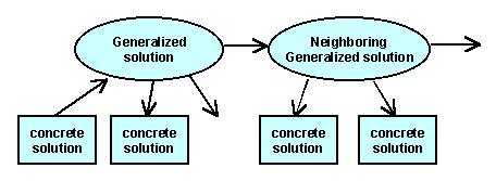
The significance of the (Solution) Generification
Method can best be understood in relation to the process similar to the
Mind Mapping [22]. With this method,
a concrete idea can associatively stimulate various related ideas in the
scheme shown in Fig. 5. This scheme is also important because it
helps us systematize our solutions at the same time (see e.g. [23]).
Fig. 5 Scheme with Solution Generalization
10.3 Usage of Results
of the Analyses in the Solution Generation Stage
It should be worthwhile to summarize how the results
of the Problem Analysis Stage serve in this Solution Generation Stage.
First, in applying each Solution Generation Method, the following information
obtained in the analyses are most useful:
-
Object Pluralization Method <== Closed
World Diagram
-
Attribute Dimensionality Method <==
Qualitative Change Diagram and Action-Property Diagram
-
Function Distribution Method <== Closed
World Diagram, Action-Property Diagaram, and Space/Time Characteristics
Analysis
-
(Solution) Combination Method <== Space/Time
Characteristics Analysis
When we search for various solutions, we are
always thinking how to overcome the difficulties expressed in the Plausible
Root Causes and, in more concretely, how to eliminate the problem effects
which may be worsened with the problem-causing Attributes and reduced with
the problem-preventing Attributes. Thus, we may relate all our efforts
and results during the Solution Generation Stage to these problem-causing/preventing
Attributes which are listed in the Qualitative Change Graphs. Associative
or developmental relations among solutions and problem-causing/preventing
Attributes are demonstrated in Fig. 6 for the case of "Picture Hanging
Kit Problem" [16]. Even though this
figure was made much later than the actual problem solving by Sickafus
[3],
understanding of this kind of structure will be helpful for us in our search
process.
Fig. 6. Relations among solutions and
problem-causing/preventing attributes
(Solution) Generalization Method is the key method
to make our solution search broader and more systematic in the scope.
The Ideal Situation (imagined in the Particles Method) and the Action-Property
Diagram (obtained by breaking it down) serves as a model of hierachical
system for our solutions. With the (Solution) Generalization Method,
we may draw our solutions in a new hierarchical system or rather draw them
as additions and modifications in the Action-Property Diagrams.
11.
APPLICATION OF SOLUTION GENERATION METHODS
In the present author's 3-Day USIT Training Seminars,
a lecture on the Solution Generation Stage is given at the end of the second
day, with two-folded intention:
-
Give the participants the time to think over the solution
methods and possible solutions overnight.
-
Save time on the third day.
It was rather difficult for the present author
and for Japanese learners to understand how to apply the Solution Generation
Methods. It was a constant requirement from the seminar participants
to explain the methods more clearly. The present author learned the
methods little by little with reference to various articles in TRIZ/USIT/ASIT
and with experiences at the seminars, and has just reached the understanding
explained in Section 10.
On the third day we have two group-practice sessions
for the Solution Generation Stage in USIT. The Instructor advises
as follows at the beginning of the morning session:
First, on the basis of the Particles Method and the
Space/Time Characteristic Analysis, try to find solution concepts rather
freely.
Then, with reference to the results of the Closed-World
Method, try to apply (especially the first three) Solution Generation Methods
intently on every member of Objects, Attributes, and Functions.
During the analysis stage with the Particles
Method (i.e., on the second-day afternoon), almost all groups have found
that they are stimulated to come up with various elements of solution ideas
and that the Action-Property Diagram is close to a hierarchical representation
of possible solutions. Thus it is natural for us to start the Solution
Generation Stage somewhat in an informal manner on the basis of the results
of the Particles Methods. Solution ideas are recorded on the whiteboard
with a lot of rough sketches, while the Action-Property Diagram are often
enhanced in parallel with these new ideas.
In 1 to 1.5 hours, most groups come up to the point
of having exhausted most of simple ideas in their mind. Thus they
start to use the Solution Generation Methods one by one. They often
feel difficulty in this application, as mentioned above, but have succeeded
in obtaining new ideas gradually. Then during the group-presentation
sub-session, they learn a number of more application cases achieved by
other groups and are encouraged through the discussions.
At the beginning of the afternoon session, the
Instructor advises in the following way:
-
Apply the Solution Generation Methods more systematically.
-
Generalize the solutions and consider the hierarchical
scheme of solutions.
-
Then, about an hour later, evaluate roughly all the
solutions obtained so far at that time and choose several important/promising
solutions among them.
-
Enhance the chosen solutions and solve any subsequent
problems accompanied with them.
The groups actually have come with slightly
different paces; some groups made much advance while others experienced
difficulties. Nonetheless, all groups succeeded in obtaining several
to twenty solution ideas to their brought-in real problems.
12.
USAGE OF TRIZ/USIT IN INDUSTRIES
After finishing the group practices of the whole
procedure of USIT, the Instructor gives the last lecture on the usage of
TRIZ and USIT in industries. The points are:
-
Use USIT in your companies just as we did in the present
Training Seminar. Nakagawa's Training Seminar can be a model of not
only training engineers in USIT but also applying USIT to real corporate
problems together with your engineers.
-
Use USIT as the thinking procedure in problem solving,
and learn more about TRIZ philosophy with textbooks and use TRIZ knowledge
bases for enhancing your knowledge.
-
Do not depend on software tools as a guide for your
thinking process.
-
Learn the activities of the USIT team at Ford as reported
by Sickafus [6, 7].
-
Introduce TRIZ and USIT in your company not in a "hurrying
and forcing strategy" but in the "Slow-but-Steady Strategy"
[2, 4].
13.
EVALUATION AND CURRENT STATUS OF USIT IN JAPAN
In the final discussion session and in the inquiry
sheets at the end of the Training Seminars, the seminar participants have
evaluated the USIT method in the following way:
-
USIT is much easier to learn than TRIZ.
-
USIT is suitable for collaborative group work.
-
USIT is applicable to real industrial problems.
-
USIT is smooth and powerful to get conceptual solutions.
-
Need to clarify a good practice of using USIT and
TRIZ software tools together.
-
Needs more case-study reports and examples to understand
USIT better.
For the models of using USIT and TRIZ software
tools (especially TRIZ knowledge bases) in a cooperative/complementary
way, the following three alternatives are proposed [2]:
-
Solve the problem with USIT in a group work, then
enhance/extend the solution ideas with TRIZ software later.
-
Use USIT for solving problems in a group, whereas
use TRIZ software for individual study and individual idea generation.
-
Use USIT for solving problems in group meetings.
The group meets several times with 1-2 week intervals, and the members
use TRIZ software to enhance their ideas during the intervals.
Two case studies worked out in the 3-Day USIT
Training Seminars were reported at MRI's users' study-group meetings by
the
seminar participants and were posted in the Web site "TRIZ Home Page in
Japan" in Japanese [24, 25]. In order
to record the cases smoothly and to encourage the participants to publish
their case studies, a template for the Seminar Case Report was handed to
them recently.
The present author is the only instructor of USIT
in Japan at moment. But as the result of seminars and Web publications,
USIT has become known pretty well among the TRIZ community in Japan.
Some of the participants of the 3-Day USIT Training
Seminars have been working actively in their companies to introduce and
apply USIT (in addition to TRIZ software tools). For instance, TRIZ/USIT
activities by Yuuji Mihara at Fuji Photo Film Ltd. was reported by himself
in "TRIZ Home Page in Japan" in Japanese [26],
and one of his application result was reported in "Nikkei Mechanical" Journal
[27]. In his company, two-membered TRIZ/USIT team is working
to train their engineers in TRIZ/USIT and to do in-company consulting of
several USIT projects in parallel.
CONCLUSION
As the results of experiences of 3-day training
seminars in Japan, an effective method of teaching and applying USIT (Unified
Structured Inventive Thinking) has been established. It is found
that USIT has well adopted the essence of TRIZ and rebuilt it into a unified
and structured procedure composed of problem-definition, problem-analysis,
and solution-generation stages. USIT has been found easy to learn
and effective and powerful to apply for solving industrial problems creatively.
Acknowledgement
The present author is grateful to Dr. Ed Sickafus
for his continuous encouragement and his valuable discussions.*13)
[*13)
E. Sickafus, Nov. 27, 2001: And I am grateful to you for your efforts
to bring USIT to the Japanese technical community. ]
REFERENCES1)
[1] See for example,
Yuri
Salamatov "TRIZ: The Right Solution at The Right Time", Insytec, 1999 (E) ;
Nikkei BP, 2000 (J).
;
Nikkei BP, 2000 (J).
[2] Toru Nakagawa,
'Learning and Applying
the Essence of TRIZ with Easier USIT Procedure', ETRIA World Conference:
TRIZ Future 2001, Nov. 7-9, 2001, Bath, UK, pp. 151-164; TRIZ HP Japan,
Nov. 2001 (E),
Aug. 2001 (J).
[3] Ed. N. Sickafus,
"Unified Structured Inventive Thinking: How to Invent", NTELLECK, Grosse
Ile, MI, USA, 1997, 488p.
[4] Toru Nakagawa
, 'Approaches to
Application of TRIZ in Japan', TRIZCON2000: The Second Annual AI TRIZ
Conference, Apr. 30 - May 2, 2000, Nashua, NH, USA, pp. 21-35. ; TRIZ HP
Japan, May 2000 (E),
February 2001 (J).
[5] "TRIZ
Home Page in Japan", WWW site edited by Toru Nakagawa. URL: http://www.
osaka-gu.ac.jp/php/nakagawa/TRIZ/eTRIZ/ (in English),
http://www.osaka-gu.ac.jp/ php/nakagawa/TRIZ/ (in Japanese).
(Note: These are abbreviated here as "TRIZ HP Japan".)
[6] Ed Sickafus,
'Injecting Creative Thinking into Product Flow', First TRIZ International
Conference, Nov. 1998, Industry Hills, CA, USA; TRIZ HP Japan, Jan. 1999
(J).
[7] Ed Sickafus,
'A Rationale for Adopting SIT into a Corporate Training Program', TRIZCON99:
First Symp. on TRIZ Methodology & Application, March 1999, Novi, MI,
USA; TRIZ HP Japan, May 1999 (J).
[8] Toru Nakagawa,
'USIT Training Seminar (Mar.
10-12, 1999, Detroit) (Instructor: Dr. Ed Sickafus) Participation Report',
TRIZ HP Japan, Mar. 1999 (J & E).
[9] Toru Nakagawa,
'USIT Case Study
(1) Detection of Small Water Leakage from a Gate Valve', TRIZ HP Japan,
Jul. 1999 (J),
Aug. 1999 (E)
[10] Toru Nakagawa,
'USIT Case Study
(2) Increase the Foam Ratio in Forming a Porous Sheet from Gas-Solved Molten
Polymer', TRIZ HP Japan, Jul. 1999 (J),
Aug. 1999 (E)
[11] Toru Nakagawa,
'USIT Training Seminar
in Japan: First Trial in a Company', TRIZ HP Japan, Sept. 1999 (J &
E).
[12] Toru Nakagawa,
"USIT - Creative Problem
Solving Procedure with Simplified TRIZ", Journal of Japan Society for
Design Engineering, Vol. 35, No. 4, 2000, pp. 111-118. (J);
TRIZ HP Japan, Apr. 2000 (E).
[13] Toru Nakagawa,
'Staircase Design
of High-rise Buildings Preparing against Fire - TRIZ/USIT Case Study -',
TRIZCON2001: The 3rd Annual AI TRIZ Conference, Mar. 25-27, 2001, Woodland
Hills, CA, USA; TRIZ HP Japan, Apr. 2001 (E & J).
[14] Toru Nakagawa,
'USIT Training Seminar
in Japan: (2) 3-day Seminar with Multi-company Engineers', TRIZ HP
Japan, Feb. 2000 (J),
Mar. 2000 (E)
[15] Roni Horowitz
and Oded Maimon: 'Creative Design Methodology and the SIT Method', 1997
ASME Design Engineering Technical Conference, Sept. 14-17, 1997, Sacramento,
CA, USA; TRIZ HP Japan, Mar. 2000 (J).
[16] Toru Nakagawa
and Ed Sickafus, 'Commentary
on "The Picture Hanging Kit Problem"', TRIZ HP Japan, Aug. 2001 (J
& E).
[17] Ed Sickafus,
"USIT Training Seminar" Course Material, Mar. 1999 (E).
[18] Ed Sickafus,
'The Sicillian Dolly', NTELLECK, LLC Web site: http://www.u-sit.net/,
Jun. 2001 (E).
[19] Roni Horowitz,
'From TRIZ to ASIT in 4 Steps', TRIZ Journal, Aug. 2001 (E); TRIZ HP Japan,
Sept. 2001 (J).
[20] staart2think.com
Web site: http://www.start2think.com/
[21] Roni Horowitz,
'ASIT's Five Thinking Tools with Examples', TRIZ Journal, Sept. 2001 (E).
[22] James Kowalick,
'Problem-Solving Systems: What's Next after TRIZ? (With an Introduction
to Psychological Inertia and Other Barriers to Creativity)', First TRIZ
International Conference, Nov. 17-19, 1998, Industry Hills, CA, USA (E);
TRIZ HP Japan, Jan. 1999 (J).
[23] Michael Lynch,
Benjamin Saltsman, and Colin Young, 'Windshield/Backlight Molding - Squeak
and "Buzz" Project - TRIZ Case Study', American Supplier Institute Total
Product Development Symposium, Nov. 5, 1997, Dearborn, MI, USA; TRIZ Journal,
Dec. 1997 (E); .TRIZ HP Japan, Sept. 1999 (J).
[24] Hiroki Ueno,
'Case Study Report at the USIT Training Seminar: Effective Methods for
Natural Air-Cooling of Electronic Devices', MRI Study Group Meeting, Jan.
2001 (J); TRIZ HP Japan, Jul. 2001 (J).
[25] Yuuji Mihara,
'Case Study Report at the USIT Training Seminar: MRI Study Group Meeting,
Nov. 2000 (J)
[26] Yuuji Mihara,
'Experiences of Introducing TRIZ/USIT in Fuji Photo Film', TRIZ HP Japan,
Nov. 2001 (J).
[27] Tsukasa Sinohara,
'Fuji Film: Improving the Filter for Extracting Plasma from Blood', Nikkei
Mechanical, Nov. 2001, pp. 72-73 (J)
Note 1) (E):
written in English, and (J): written in Japanese.
About the Author
Toru Nakagawa is currently Professor of
Informatics at Osaka Gakuin University. Since he was first exposed
to TRIZ in May 1997, he endeavored to introduce it into Fujitsu Labs for
which he was working. After moving to the University in April 1998,
he has been working for introducing TRIZ into Japanese industries and academia.
In November 1998 he founded the public WWW site "TRIZ Home Page in Japan"
and serves as the Editor. He is currently working to introduce USIT
as an easier TRIZ procedure.
He graduated the University of Tokyo in chemistry
in 1963, studied at its doctoral course (receiving D. Sc. degree in 1969),
became Assistant in Department of Chemistry, the University of Tokyo in
1967; he did research in physical chemistry, particularly experiments and
analyses in the field of high-resolution molecular spectroscopy.
He joined Fujitsu Limited in 1980 as a researcher in information science
at IIAS-SIS and worked for quality improvement of software development.
Later he served as a managing staff in IIAS-SIS and then in R&D Planning
and Coordination Office in Fujitsu Labs.
E-mail: nakagawa@utc.osaka-gu.ac.jp
Last updated
on May 16, 2002. Access point: Editor:
nakagawa@utc.osaka-gu.ac.jp