TRIZ Application 2: Easy Practice of Applying TRIZ -- Concepts and Application of USIT (Unified Structured Inventive Thinking)
Toru Nakagawa (Osaka Gakuin University, Professor Emeritus)
TRIZ Application 2: Easy Practice of Applying TRIZ -- Concepts and Application of USIT (Unified Structured Inventive Thinking) |
|
| Toru Nakagawa (Osaka Gakuin University, Professor Emeritus) |
|
| "Standardization and Quality Control" (Japanese Standards Association), Vol. 66, No. 2, pp. 31-36 (2013), Special Issue on TRIZ | |
| [Posted: May 8, 2013] |
For going back to Japanese pages, press buttons.
Editor's Note (Toru Nakagawa, Apr. 14, 2013)
This is the English translation of my paper
published in the Special Issue on TRIZ of the "Standardization and Quality Control". The journal is the official monthly magazine published by the Japanese Standards Association (JSA), which is a semi-official organization for promoting standardization, e.g. ISO, JIS, and QC, in Japan. The Special Issue contains 8 papers, in 53 pages in total, as shown in the parent page
. I am grateful to the Japanese Standards Association for their kind permission of reposting all the papers in the present Web site.
This is the 5th paper in the Special Issue, following three overview papers and one TRIZ application paper. In the present article, I introduce USIT as an easy and effective way of applying TRIZ. USIT was originally developed by Dr. Ed Sickafus in 1990s. And we introduced it into Japan and further developed it in two significant aspects, i.e., constructing a system of USIT Operators (by reorganizing TRIZ tools) and recognition of the basic scheme (named Six-Box Scheme). I am introducing USIT here in my own way on the basis of such up-to-date understanding.
Two case studies of USIT application are demonstrated here. The first one is an early example carried out at Fuji Photo Film Co. for improving the filter to separate plasma from blood. The second one is a case of developing a new type of 'Mom's bicycle to carry two children'. The front child seat is fixed to the frame of the bicycle by separating the steering-handle shaft from the front-wheel fork shaft. The thinking process in USIT is explained in some detail.
In the Japanese page
I post the original PDF version published in the journal and also an HTML version for readers' convenience. In this English page, the paper is posted in English translation in HTML with some additional notes in the references.
Table of Contents:
1. History and Overview of USIT
2. Concept of the Six-Box Scheme and the overall procedure of USIT
Six-Box Scheme, USIT procedure, USIT Operators
3. USIT Case Study (1) Improving the method to separate plasma from blood for testing
Problem definition, Problem analysis, Idea generation, Solution construction, Concluding remarks
4. USIT Case Study (2): Mom's bicycle for safely carrying two children
Problem definition, Problem analysis (Time-characteristic analysis, Functional analysis), Idea generation, Solution construction, Notes on USIT Operators, Concludng remarks
| Top of this page | Top of the paper | 2. Six-Box Scheme | Case Study 1 (Filter) | Case Study 2 (Bicycle) | Ref. | TRIZ Special Issue, Parent page |
Japanese page |
TRIZ Application 2:
Easy Practice of Applying TRIZ --
Concepts and Application of USIT (Unified Structured Inventive Thinking)
Toru Nakagawa
(Osaka Gakuin University, Professor Emeritus)
As a method of practical execution of applying TRIZ we have USIT (Unified Structured Inventive Thinking). It was originally developed by Ed Sickafus in USA in 1990s under the influence of TRIZ, and has been revised and used in Japan in 2000s. USIT has a streamlined procedure for creative problem solving. It is easy to learn and apply. Various TRIZ tools have been reorganized and unified into a much simpler and practical procedure.
In the present article, the concepts of USIT are introduced along with two case studies of application.
1. History and Overview of USIT
A trial of simplifying the overall process of TRIZ was made in early 1980s in Israel. They built SIT (Systematic Inventive Thinking), which had only 4 methods for solution generation. Ed Sickafus of Ford Motor Co. in USA learned TRIZ and SIT, and on the basis of the latter he built an overall procedure for creative problem solving, and named it USIT in 1995 [1]. He conducted 3-day USIT trainings to 1000 engineers and applied USIT to a number of real projects in Ford for 3 years.
In 1999 Toru Nakagawa learned USIT at Sickafus' 3-day training and introduced it into Japan as "an easy way of learning and applying TRIZ". Later he reorganized all the TRIZ tools for solution generation into a system of "USIT Operators" (in 2002) [2]. And he recognized its basic framework as "Six-Box Scheme" in contrast to the conventional "Four-Box Scheme" in TRIZ as well as in science and technology, and demonstrated it as "A New Paradigm for Creative Problem Solving" (in 2005) [3]. USIT has been introduced into a number of industries in Japan and used in parallel to other practice ways of TRIZ.
Below in this article, I will demonstrate the concepts and usage of USIT as the new paradigm for creative problem solving.
2. Concept of the Six-Box Scheme and the overall procedure of USIT
The Six-Box Scheme, a new paradigm of creative problem solving [3], is illustrated in the form of a data-flow diagram in Fig. 1.
Fig. 1. Six-Box Scheme: A New Paradigm of Creative Problem Solving
(in a data-flow diagram representation)The scheme may be represented in a flowchart as shown by bold face fonts in Fig. 2. The methods shown in smaller fonts in each process represent some tools specific to USIT. (Note: The "Six-Box Scheme" is a conceptual paradigm, while USIT is a specific procedure concretizing the scheme.)
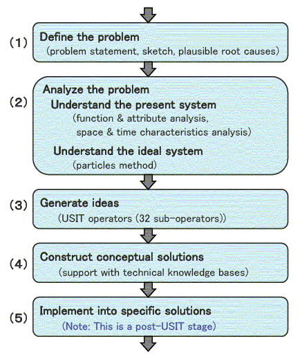
Fig. 2. Flowchart representation of the Six-Box Scheme and the overall procedure of USIT
The crucial differences of the Six-Box Scheme from the conventional Four-Box Scheme in science and technology and in TRIZ are:
- The third box (top left in Fig. 1) is not a generalized problem in a model chosen from elsewhere but a whole and deep understanding of the present problem.
- The fourth box (top-right in Fig. 1) is not a generalized solution of the chosen model being suggested as a hint for a new solution concept but an idea of a new solution concept.Concretizing the new scheme, USIT has the advantages:
- It has standard methods of problem analysis to be used universally to different types of problems.
- It has a system of USIT Operators (32 sub-operators in 5 classes) for the effective generation of ideas.
- Following the analysis of problem, ideas for new systems are generated naturally and smoothly (as shown by the by-passing arrow in Fig. 1).Now let me explain about the USIT Operators. In the early stage of introducing USIT in Japan, we felt difficulty in understanding and applying the solution generation methods, because Sickafus explains his five methods rather briefly and demonstrates its intuitive applications.
Hence we worked to reorganize all the different and many solution generation methods developed in TRIZ into the USIT five solution methods (see Fig. 3). Then the enriched five methods of USIT were further classified into a hierarchical system, having 32 sub-operators of 5 classes (or 5 main operators) [2].
Fig. 3. All the TRIZ solution generation methods were reorganized into USIT Operators
Examples of USIT Operators and their usage will be demonstrated later in the second case study. Two sub-operators demonstrated there are: Sub-operator (1c) Divide the object and Sub-operator (3b) Divide the combined functions and assign them to different objects. As shown by these names, we apply them onto some elements (or aspects) of the system.
3. USIT Case Study (1) Improving the method to separate plasma from blood for testing
As an example of applying USIT in the early days in Japan, let me introduce a case carried out at Fuji Photo Film Co. (currently Fuji Film Co.) for improving their product [4].
[Problem Definition] The task was to improve their product of emergency blood testing equipment, specifically in the process of extracting plasma (i.e., the liquid part) from the test blood. The filter needed to be improved in efficiency by avoiding from clogging.
For obtaining the plasma of 0.185 ml, their equipment needed blood of 3 ml. The amount of blood should be reduced to less than 1 ml.
[Problem analysis] In the conventional equipment the blood was sucked through the filter shown in Fig. 4. The filter had two layers: the first layer (5 mm thick) is made of glass fibers having larger gaps than blood cells, while the second layer is made of porous polysulphone membrane having finer pores. The diameter of the filter was about 20 mm.
The difficulty was that with the glass fiber layer having larger gaps, the blood cells could not be captured well, whereas with the layer having smaller gaps the blood cells clogged the filter.
Understanding of the problem system was obtained through the space & time characteristic analysis in USIT. The phenomena of capturing blood cells at the glass fiber filter were considered closely along the time.
Physical experiments were made for examining their hypotheses. During the process of sucking the blood through the filter, the filter was instantly frozen with liquid nitrogen and sliced along the filter axis to observe the amount of captured blood cells. Curves shown in Fig. 4 are the captured blood cell distributions along the filter axis at three timings. Comparing the distributions at time (2) and at time (3), the blood cell density in the middle of filter thickness was found reduced with time. This fact made the team realized the actual process in the filter: "the blood cells once captured by the fibers are later released to flow down the stream and are captured again repeatedly." Photos taken by electronic microscopes also convinced the team of this phenomenon.
Fig. 4. Structure and behavior of the conventional plasma filter.
The graph in the right shows the distribution of captured blood cells along the filter axis, at different timings.[Idea generation] Thus the team obtained the idea of making the glass-fiber layer longer. When the blood is sucked through the filter, the blood cells flow down in the stream of plasma but are captured and released by the glass fibers repeatedly and hence are delayed in the stream. Thus the difference in the flow velocity of blood cells and plasma can be used for separating them. The diameter of the filter can be reduced in such a solution.
[Solution construction] Finally the filter, conventionally of a flat disk type, was made into a thin pipe type. This solution was successfully installed in their new product.
[Concluding remarks] This problem was brought in by an engineering division to the TRIZ/USIT group. The group together with the engineers had 6 meetings for 2 to 3 hours each to tackle the problem by using USIT. A large number of ideas (besides the above) were generated and several patents were filed as the results. The lesson of this case study was the importance of getting free from psychological inertia, i.e., "Filter is used to block larger particles" in this case.
4. USIT Case Study (2): Mom's bicycle for safely carrying two children
This case study was obtained at Nakagawa's 2-day USIT training seminar of engineers coming from different companies in March 2008 and refined two months later [5]. In the training seminar, 20 engineers who were new to TRIZ/USIT took part. Lectures of introductory TRIZ and full process of USIT were given and group practices of solving real problems by the use of USIT were carried out in 3 groups, addressing different problems.
[Problem Definition] This problem was proposed by Nakagawa with the trigger of a TV news broadcast a few days before. It said the Police Office had decided, as a response to strong requests from mothers, to make it allowable in near future to carry two children on a bicycle if bicycles safe enough for such a purpose were developed. (Note that at that time in Japan carrying two children on a bicycle was officially prohibited by law, even though many parents actually violated it.) The five members of the group were coming from different fields of engineering, but easily understood the problem and the significance of solving it.
[Problem analysis] (1) The group first applied the time-characteristic analysis. It was noticed that the dangerous timings for the moms were:
- when putting the children one by one on the standing bicycle,
- when starting to run the bicycle,
- when running very slowly e.g. at the up-hill slope,
- when dropping a leg to hold the bicycle during staggering or stopping,
- when unloading the children one by one from the standing bicycle, etc.This confirmation was useful later during the discussion whether to place the children's seats at high or low positions. There was an solution concept to set the child seats at higher positions so as to make the bicycle more stable while running, just as taller stilts are more stable. An opposite solution concept was to set the seats at lower positions to make the bicycle safer while it is running very slowly or stopping. The latter solution concept was adopted by the group on the basis of the understanding of dangerous timings.
(2) Functional analysis is also an important method regularly used in USIT. In Fig. 5 the functional analysis diagram is shown for the bicycle system where a parent is carrying two children, one in the front seat and the other at the back seat. Note that the parent and children are included in the system.
The USIT guideline for drawing the functional diagrams are:
- To place the most important object(s) (or component(s)) of the system at the top of the diagram.
- To place any object(s) directly serving (or having useful functions) for the above object at the lower position and to draw an upward arrow with the annotation of the function.
- To represent the objects and functions in generic terms instead of specific ones.
Fig. 5. Functional diagram of a bicycle system where a parent carry two children; during running normally; an typical bicycle structure about 15 years ago.
By following these USIT guidelines, the functional diagram in Fig. 5 is constructed in the manner just like a side view of the parent and children running on a bicycle. The diagram also shows clearly that the principal functions of the system are:
(a) to support (the bicycle structure and the persons),
(b) to provide a driving force, and
(c) to change or control the direction (to go).From the beginning, the focus of the problem was where and how to support the front child seat. Fig. 5 represents an old structure where the front child seat is hung on the horizontal bar of the steering handle; this was typical in Japan about 15 years ago.
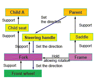
At the time of the training seminar, as well as at present in 2013, an improved structure was popular, where the front chair is placed on the top of the fork shaft of the front wheel by making the steering handle two-branched under the seat. The functional diagram of the improved design may be shown in Fig. 6(A) for the relevant part. The steering operation has become slightly easier than before but still has the drawback of being heavy and unstable because the moment of inertia is large to turn the wheel and the child together.
 |
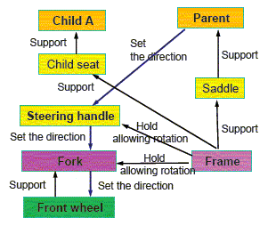 |
| (A) Currently prevailing design (2013) | (B) Proposed design (B) in the present study |
Fig. 6. Functional analysis diagrams (part):
[Idea generation] We, the practice group, generated various ideas to improve the conventional system. Some of our solution concepts (A) were based on the conventional design concerning to the supporting structure of the front child seat, as shown in Fig. 6(A).
We also built different conceptual solutions (B), where the front child seat is supported/fixed directly on the bicycle frame. In such a system, however, the front child seat is inserted between the parent seat and the steering handle axis and hinders the parent from rowing the pedal freely.
About 2 months after the training seminar we got a new idea, i.e., "to separate the steering shaft and the fork shaft for turning the front wheel direction and to place the former at the parent hands while the latter ahead at the front wheel." Functional analysis diagram of the new idea is shown in Fig. 6(B). On reading this idea via email, another member of the group suggested that it should be easy to convey the motion of the steering handle to the rotation of the fork shaft by using a link mechanism.
[Solution construction] On the basis of the new ideas we built a solution concept as shown in Fig. 7. For emphasizing the idea of new mechanism, we place the two children in the front seats in Fig. 7; but it is also a choice to place one in the front and the other at the back.
The child seats are stably fixed to the bicycle frame, and the steering handle can turn the fork shaft of the front wheel easily via the link mechanism without any load of turning the child.
A bit of driving exercise may be necessary; thus such a chance of test driving should be provided at the bicycle shops. The duration time period when two children need to be carried on a bicycle may be 2 to several years. Thus a leasing scheme may be more suitable than the ordinary purchase scheme.
Fig. 7. A bicycle of our proposal for carrying two children, where the children seats are fixed to the frame. Choice of one child in the front and the other at the back is also all right.
[Notes on USIT Operators] The ideas generated above may be explained here in terms of the USIT Operators:
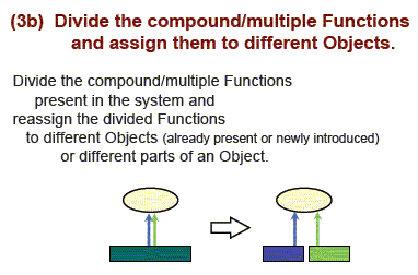
First, the idea of "to support the front child seat by the frame instead of by the steering bar or by the fork shaft" can be suggested by the USIT sub-operator (3b), see left part of Fig. 8.
The sub-operator advises "to divide the combined (or multiple) functions and assign them to different objects (or components)".
The fork shaft has the principal function of turning the direction of the front wheel, but in the design shown in Fig 6 (A) it is also given the function of supporting the front child sheet. Thus the sub-operator (3b) suggests to transfer the function to support to some other object. The frame or body of the bicycle should naturally have the function to support the seats.
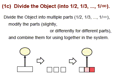
This kind of idea is also recommended by Suh's Axiomatic Design principle.The difficulty of the preliminary idea of fixing the front seat to the frame was the lack of space for rowing the pedals. The difficulty comes from the psychological inertia that the steering shaft and the fork shaft are combined in a line. The USIT sub-operator (1c) (see right part of Fig. 8) suggests to divide the steering shaft and the fork shaft.
The sub-operator (1c) suggests the division, in general, for various reasons such as "to make the parts mutually independent", "to increase the flexibility", "to separate an undesirable part and eliminate the interference", etc.
For recombining the divided parts and using them together, we needed the mechanisms of holding the steering shaft by the frame and of conveying the rotational angle of the steering shaft to the rotation of the fork shaft by use of a link.
 |
 |
| (A) USIT sub-operator (3b) | (B) USIT sub-operator (1c) |
Fig. 8. Two examples of USIT sub-operators
[Concluding remarks] After we presented this case study at TRIZ conferences, we sent this proposal to the Technical Center of Japan Bicycle Promotion Institute. Their responses were:
"Your conceptual solution (A) is essentially the same as the improvement proposals made recently by many bicycle manufacturers. We are impressed with the appropriate results obtained quickly by engineers non-relevant to bicycle design with your USIT thinking process.
Concerning to your conceptual solution (B), we know similar ideas in overseas countries, where the steering shaft and the fork shaft are separated widely and a boat-shaped cabinet for two children is placed in between. "
We have not found any bicycle manufacturer who adopts our conceptual solution (B), as shown in Fig. 6(B) and Fig. 7. However, I believe that the value of our idea will be realized in future.
In the present article we do not have enough space to explain all the methods in the USIT process. Please refer to [6] (in Japanese).
References
[1] Ed Sickafus: "Unified Structured Inventive Thinking: How to Invent", NTELLECK, Grosse Ile, MI, USA (1997).
[2] Toru Nakagawa, Hideaki Kosha, and Yuji Mihara: 'Reorganizing TRIZ Solution Generation Methods into Simple Five in USIT', ETRIA World Conference "TRIZ Future 2002" held at Strasbourg, France, on Nov. 6-8, 2002 (E); TRIZ HP Japan, Sept. 2002 (J)
, Nov. 2002 (E)
.
[3] Toru Nakagawa: "A New Paradigm for Creative Problem Solving: Six-Box Scheme in USIT without Depending on Analogical Thinking", 27th Annual Conference of the Japan Creativity Society, Oct. 29-30, 2005, Tokyo (J); TRIZ HP Japan, Nov. 2005 (J)
, Apr. 2006 (E)

[4] Toshifuru Ito, Yuji Mihara, et al. (Fuji Photo Film), 2nd Japan IM Users Group Meeting, 2001 (J).
[5] Tetsuya Sudo, Hiroshi Sakata, Toru Nakagawa, et al.: 'USIT Case Study: A Mom’s Bicycle for Safely Carrying Two Children', 4th Japan TRIZ Symposium, Sept. 10-12, 2008 (J & E); TRIZ HP Japan, Jan. 2009 (J)
; TRIZCON2009, Mar. 16 - 18, 2009 (E); TRIZ HP Japan, May 2009 (E)
[6] Toru Nakagawa: 'Introduction to USIT: A Simple Method for Creative Problem Solving', in "Machine Design" journal, Aug. to Dec. 2007; TRIZ HP Japan, Jul.- Dec. 2007 (J)
Additional USIT references for English readers (TN, Apr. 14, 2013)
[7] Ed Sickafus: USIT Web site: URL http://www.u-sit.net/ ;
eBook "USIT Overview" is downloadable. (Japanese translation of eBook in TRIZ HP Japan).
[8] Ed Sickafus: USIT NewsLetters and Mini Lectures (originally published in 79 issues from Nov. 2003 to Mar. 2009); English version in TRIZ HP Japan
; Japanese translation in TRIZ HP Japan
.
[9] Toru Nakagawa: Extension of USIT in Japan: A New Paradigm for Creative Problem Solving, Japan TRIZ Symposium 2008; TRIZ HP Japan

| Top of this page | Top of the paper | 2. Six-Box Scheme | Case Study 1 (Filter) | Case Study 2 (Bicycle) | Ref. | TRIZ Special Issue, Parent page |
Japanese page |
Last updated on May 8, 2013. Access point: Editor: nakagawa@ogu.ac.jp