TRIZCON2000: The Second Annual AI TRIZ Conference, Sheraton Tara, Nashua, NH, USA, Apr. 30 - May 2, 2000, pp. 177-182.
Editor's
Preface for English and Japanese Versions (Toru
Nakagawa, July 27, 2000)
This paper is a TRIZ case study presented by Ian Mitchell at the TRIZCON2000 conference last May, as shown above. At the conference, as reported by the present editor in his personal TRIZCON2000 participation report in Japanese in this site, very few case studies of application of TRIZ were presented in technological terms from industries, mostly due to companies' secrecy policies. Under such a situation, this paper is precious because of its frank and detailed description how they applied TRIZ to a real problem.
The value of this paper as a case study is not at the point that it has found a high-degree technical solution by use of TRIZ. Rather, it is valuable because it describes that in an industrial company a small group of people lead by the present author have started to learn about TRIZ, holding lunchtime meetings every week, and tried to apply TRIZ to real problems brought in by colleagues. The process of their solving a particular problem is described frankly in technical terms without touching any technical secrets. They used the software tool TechOptimiser in their analysis: first they constructed a functional model of their problem system, and tried to apply the trimming method. At one stage during the trimming process, the group's thinking way was changed drastically and was led to a very simple and efficient solution. This paper encourages us TRIZ beginners to apply the methodology in a simple way just like this. Without depending on TRIZ experts and TRIZ consultants so much, the group is making progress in mastering TRIZ and applying it to their real problems. We can do so, too.
I read this paper just after the conference (because I missed the presentation due to parallel sessions) and asked the author to give me a permission of translating the paper into Japanese and posting here. The author replied me that he had received similar accesses from Nikkei Mechanical Journal and Mitsubishi Research Institute. So, the three parties in Japan decided to cooperate together, and obtained the permission by the author and his company to translate this paper into Japanese and to post it in several ways.
We, "TRIZ Home Page in Japan", are very grateful to the following people for their kind permissions of my translating the paper into Japanese and posting it here together with the full English text.
Mr. Ian F. Mitchell (Ilford Imaging UK Ltd., UK)
email: Ian.Mitchell@ilford.com
Ilford Imaging UK Ltd.
Web site: http://www.ilford.com/
The Altshuller Institute for TRIZ Studies
Web site: http://www.aitriz.org/
This paper has been introduced in Japan in the following several ways:
Nikkei Mechanical Journal (in Japanese): (a) one-page article (June
issue), (b) Web site
Mitsubishi Research Institute (in Japanese): (a) review presentation at
the Working Group meeting, (b) Web site
TRIZ Home Page in Japan: (a) full English text, (b) full Japanese
translation
Summary
During the slide bead coating process a thick edge
of emulsion is laid on the extreme outer edges of the coating.
A system consisting of a separator vessel, a vacuum
pump, a holding tank and a nozzle had been designed and built to remove
the excess emulsion from the edge of the wet coating.
Continuous maintenance was needed to keep
the system operating and to stop the vacuum pump from being blocked by
emulsion being carried over during the removal process.
To overcome these problems a series of components
were added including a spray inside the separator vessel, a filter
before the vacuum pump and eventually a second separator vessel.
This approach did not reduce the level of maintenance
or improve the systems performance.
The newly acquired Techoptimiser Professional Edition
software and the group who had been trained in its use were asked to come
up with an improved method of Thick Edge Removal.
By using TOPE the original system was reduced
from twelve components down to just two components costing just a few pounds,
requiring only occasional cleaning and using a resource from the original
system.
An additional benefit has also emerged from the
development of the new system.
1. The Photographic Coating Process
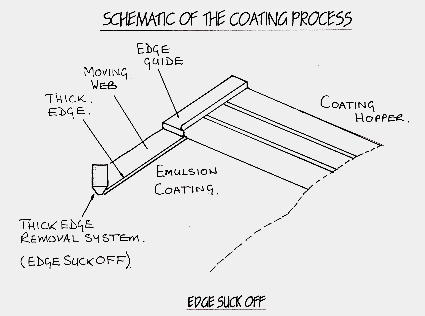
One of the numerous methods for coating materials that are light sensitive is the slide bead process. This method of coating has been used successfully for many years for achieving the required accurate level of liquid distribution across the width of the material to be coated.
This process requires the cascade/ hopper to be
positioned extremely accurately and very close to the substrate to be coated
so that the liquid can pass down the inclined slide and pass across the
coating gap (see fig1).
 |
|
| . | Fig. 1. Shematic of the coating process |
At each outer edge of coating a thick edge is generated by an edge guide to maintain positional accuracy of the edge of coating on the substrate. The thick edge also maintains the stability of the sheet of liquid passing across the gap and prevents necking from occurring which in turn would create an uneven edge to the coating and thus generate undue waste.
Once the thick edge of emulsion is on the base
it has served its purpose. Due to the nature of the drying process the
thick edge then has to be removed as the thick line of emulsion requires
considerably more drying than the rest of the liquid sheet.
2. Edge Suck Off System History
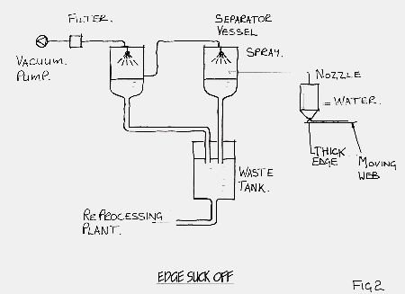
A system was designed to remove the thick edge
of emulsion from the surface of the moving web. This consisted initially
a vacuum pump, a separator vessel, a waste tank, a delivery pipe and a
nozzle (see fig 2).
 |
|
| . | Fig. 2. Old design of the edge suck off system |
The idea behind the design was to suck the excess thick edge from the base where it would mix with the surrounding air to form a mixture. It would then be drawn along the delivery pipe into the separator vessel, the liquid and air mixture would then separate. The liquid falling onto the surface of the waste whilst the air would follow the route to the vacuum pump.
The delivery pipe entered the separator vessel tangentially to try and reduce the velocity of the mixture, hence giving it more chance to separate.
In the first instance the vacuum pump became blocked by emulsion which did considerable damage. To overcome this problem a filter was placed between the separator vessel and the vacuum pump but although there was some improvement after a period of time the vacuum pump again became blocked. At this time a spray was added into the top of the separator vessel to try and stop the carry over from the separator vessel into the vacuum pump.
During this period products were changing and it became necessary to dilute the emulsion being picked up from the base with warm water to stop the nozzle and delivery pipe from becoming clogged.
There were still problems around separation and
so yet another separator vessel with spray was added into the configuration.
3. Introduction of TRIZ and Techoptimiser to Ilford Imaging.
After two presentations by Graham Rawlinson of Next Step Associates, a visit to a seminar given by Ellen Domb in London and two presentations by myself to the Ilford Management Team it was decided to purchase a single licence for the Techoptimiser Professional edition (TOPE). This was followed by a two day training course for eight people and after that I set up a weekly lunch time session for that group to meet and not only solve problems but also to educate ourselves in the tools of TRIZ.
The group were asked to look at the Edge Suck Off System and to see if it could be improved.
The following is how the group analysed the system. Then solved the problem using TOPE and how there were radical changes in the groups thoughts and ideas during the process.
What were the Objectives:-
1. To improve system performance:-
Separation
of the emulsion was not happening inside either of the vessels.
2. To reduce maintenance:-
The
system had to be stripped on a regular basis with parts being replaced
because of blockage.
3. To stop the vacuum pump and filter from
clogging:-
Even
with the protection of two separator vessels the vacuum pump and filter
were still becoming clogged.
4. To stop additional components from being
added to the system:-
It
was quite clear that all previous efforts had just complicated the problem.
Compromise had been used everywhere.
4. The Path through TOPE to solve the problem
The first thing to do when using the TOPE software is to fill out the objectives and limitations around the existing system, then build a function model of the system.
By doing this you are aware of the constraints you are working within and it is possible to argue that you have thought about the ideal system.
All the components were built into the function
model showing useful, harmful and insufficient actions linking the various
components.
The initial function model can be seen in fig
3.
| . | Fig. 3. Initial function model on TOPE |
Immediately it is possible to see that there are a series of contradictions in the existing system.
The delivery pipe has the useful effect of transporting the mixture but the detrimental effect of causing the mixture to solidify during transportation
The nozzle water has the useful effect of diluting the coating solution but the harmful effect of coagulating the coating solution.
There is the useful effect of the air aiding the transport of the coating solution but the harmful effect of mixing with it which, with the existing system requires it to be separated.
There is also the insufficient effect between the separator vessel and the mixture itself and the insufficient effect that the filter was having on the vacuum pump.
Finally there is the problem of the spray in the
top of the vessels having a harmful effect.
5. Initial Ideas
From this some initial ideas of what could be done with the system were discussed.
1. Improve separation of the emulsion within the vessel to stop the emulsion getting past the filter and into the vacuum pump.
2. A method to stop the mixture clogging the delivery pipe needed to be found.
3. At this point there was still much discussion within the group about solving the problem without having analysed the situation properly.
All the links between the components were then assigned values to show their importance within the system.
This was done by consensus within the group and
the “expert” who new the system.
6. Begin to Trim
The component that came out at the top of the list for the trimming process was the water spray as it was close to the product and also having a harmful effect. It was not stopping the emulsion from carrying over into the vacuum vessel.
With this removed from the system it did not look very different from before but it would save some energy costs. The question of improving the system performance still had to be answered so the trimming process was continued. Discussion still centred around methods of separating the emulsion from its carrier, the water and air mixture.
The next component on the list was the separator
vessel. At this point the question was asked how can there be a system
to separate emulsion without the separator vessel?
There was now a radical change in our direction
of thinking. If the separator vessel could be eliminated why try
and separate the mixture at all? In its present form the material
we were doing all this work to was scrap. There must be a way of
getting the material from where it was to where it was needed, with the
minimum amount of work.
We did not stop at this point and continued with the trimming process to see if there was a way of reducing the system itself to a much fewer number of components than it was presently built from.
Further ideas discussed at this stage included the use of a liquid ring pump. This would be able to handle the mixture of air, emulsion and water but would still consume a relatively high level of energy to keep the system working. Further investigations also suggested that there would be a considerable increase in the amount of water that we were presently using. There was also the feeling that it would still be far away from an ideal system
We were now at the stage of completely removing the vacuum pump and filter and just leaving the nozzle, nozzle water and the delivery pipe.
The system was considerably reduced from the original starting point of eleven components. All that was left was the nozzle through which the liquid must travel, the delivery pipe from the nozzle to the reprocessing plant, water to stop the emulsion from clogging the nozzle, the emulsion itself and the surrounding environment, air.
Fig 4 shows the trimmed model.
| . | Fig. 4. Trimmed functional model on TOPE |
7. Towards the Ideal System
What was needed was a method of removing the liquid from the web and sending it to our reprocessing area by only using water and our existing nozzle.
Now with a much trimmed down system there were still some questions to be answered that were raised at the very beginning.
1. How to overcome “solidifies” in delivery pipe
2. How to get the emulsion off the moving web and into the delivery pipe with just the available resources.
By using the Prediction module in conjunction with the 76 Standard Solutions the following concepts were developed.
Something that came up in our search was that Rhythm co-ordination was not an option. The energy increase would cause greater coagulation. This was something that could not be considered.
Surround the emulsion, air, water mixture with a new substance.PTFE lined delivery pipe.
Co-axially inject water around the mixture to keep it away from the pipe wall.
Introduce a modified substance into the emulsion at the point of removal from the base i.e. wetting agent
By now moving to the physical effects data base a method needed to be found whereby a liquid could be lifted from the surface of the moving web by using the available resources of water and nozzle.
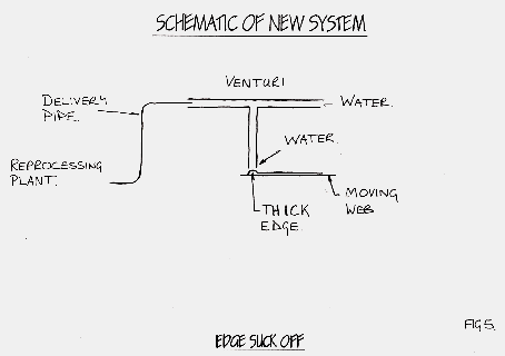
This came in the form of the Venturi nozzle using the Bernoulli effect. This fitted in perfectly with the requirement of just using water and the nozzle to remove the emulsion from the base material.
After a small amount of searching a supplier was found who was able to supply a nozzle to match the demands of the system.
This has since been thoroughly been tested and proven to be very effective.
The issue of clogging in the delivery pipe has been resolved by the use of water from the venturi nozzle diluting the emulsion to a greater degree than before.
There is also the added benefit that when the mixture reaches the reprocessing plant it does not have to be diluted further. The water used in the venturi nozzle does this well enough not to have to dilute it again.
Fig 5 shows the schematic of the built system.
 |
|
| . | Fig. 5. Shematic of the new system for edge suck off |
8. Conclusions:-
By using TOPE the system went from 12 components
to just two components.
The venturi nozzle and the delivery pipe.
Maintenance has been virtually eliminated.
A radical change in the direction of the groups thinking took place during the analysis.
The emulsion is still removed from the edge of the moving substrate without detriment to the product,
We no longer have to dilute the emulsion once it gets to the reprocessing area as the water in the venturi does that for us,
The device only costs £90
Bibliography:-
Techoptimiser Professional Edition V3.0 Training
manual
The Innovation Algorithm: G Altshuller
Tools of Classical TRIZ: Boris Zlotin Alla
Zusman
TRIZ: The right solution at the right time: Yuri
Salamatov
| Top of this page | Japanese
page |
| Home Page | New Information | Introduction to TRIZ | TRIZ References | TRIZ Links |
| TRIZ News & Activities | TRIZ Software Tools | TRIZ Papers and Tech Reports | TRIZ Forum |
Last updated
on July 27, 2000. Access point: Editor: nakagawa@utc.osaka-gu.ac.jp