Fig. 8.1 [Project Data] display in [TechOptimizer Module]:
To describe your project
8.
To describe the outline of the user's system in the problem
(TechOptimizer Module: Part 1. Basic part)
So far we have learned about three
modules which offer databases; they are:
| [Prediction Module]: | Trends and "standard means" for improvement ([Method tree]) |
| [Effects Module]: | Science and technology principles (Effects) and their examples |
| [Principles Module]: | Principles of Invention and the "Contradiction Solving Matrix" |
Now let us learn the [TechOptimizer
Module], which is the entrance module of the
[TechOptimizer Pro] software tool.
This module does not have any database to offer,
and hence you can do nothing on
it without your input of the problem you want to solve.
If you have understood the usefulness
of the TRIZ-methodology software tool by now,
you would like to master this module
for solving a problem. In real practice of solving a
problem, it is necessary to clarify
the problem itself, to manage the solution process, and
to record/report intermediate and
final solutions. For these purposes this module serves
you as the management tool to be
called at first.
8.1 To describe your own problem/project
[Operation:
When you initiate the [TechOptimizer Pro] program, the main display of
this
[TechOptimizer
Module] appears. In response to the question in the [Welcome to
TechOptimizer]
window, you should press the [New Project] button. The [Project Data]
display appears
as in Fig. 8.1,
and you should describe your problem in the windows. At
the lower
left of the display, you may open the [Project Data] menue and then click
the
[Team] button
to describe about your project team and schedule. ]
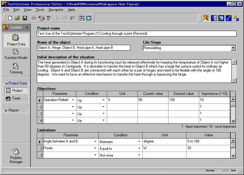
Fig. 8.1 [Project
Data] display in [TechOptimizer Module]:
To describe your project
You should describe the following
items about your own problem (or project) :
| Project name | |
| Name of the object: | object system in the problem |
| Initial description of the situation: | statement of the problem situation |
| Objectives: | Objective parameters and
their current values, desired values, and
importance (in 0 - 10 grades) |
| Limitation: | Constraint parameters and their value ranges |
| Team: | a list of project members |
| Schedule: | starting date and finishing date |
8.2 Functional model of the current system
For making your problem more clearly,
you are requested to represent a function model
of your current system (or your
new system under consideration) in a diagrammatic form.
[Operation:
In the main display of [TechOptimizer Module], you may click the [Function
Model] button
at the left end to enter the functional analysis mode. The main display
of
the functional
analysis mode offers a drawing tool. By operating the simplified,
built-in
drawing tools,
you may draw the function model of your system, as demonstrated in Fig.
8.2.
]
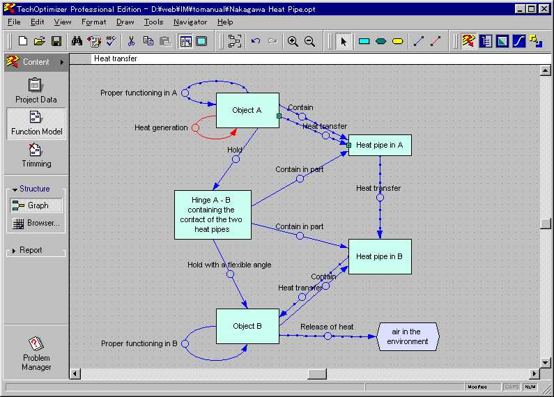
Fig. 8.2
[Function Model] display of [TechOptimizer Module]:
A drawing example of the functional model
For representing a function model,
[TechOptimizer Pro] uses the following five elements:
| Component: | (part, system component) | a rectangular node |
| Supersystem: | (upper-level component, environment, external component) | a hexagonal node |
| Product: | (product, output) | a rounded-rectangular node |
| Useful action: | (desirable function/interaction/effect) | a blue arrow |
| Harmful action: | (undesirable function/interaction/effect) | a red arrow |
You may operate the drawing tools
for the function model in a way common to general-
purpose drawing software such as
MacDraw and PowerPoint. [TechOptimizer]'s built-in
tools are well customized for drawing
the function model and very easy and effective to
use. As a result of customization,
you can describe the functions (or actions) between
system compoments in detail and
such input data are used internally in various aspects of
the functional analysis.
[Operation:
If you click a small circle at the middle point of an arrow between nodes
in
the functional
model, a [Link Analysis] window appears as shown in Fig.
8.3. At the left
in it, in
the [Actions] window, you may enter a name of function between the nodes
(multiple
functions are allowed between a pair of nodes, if necessary). Then,
you specify
whether the
function is useful or harmful for the objective of the system. If
you further
specify physical
parameters to represent the function in the [Parameters] window, the
right part
of the [Link Analysis] window opens to allow you to input further details
of the
parameters.
]
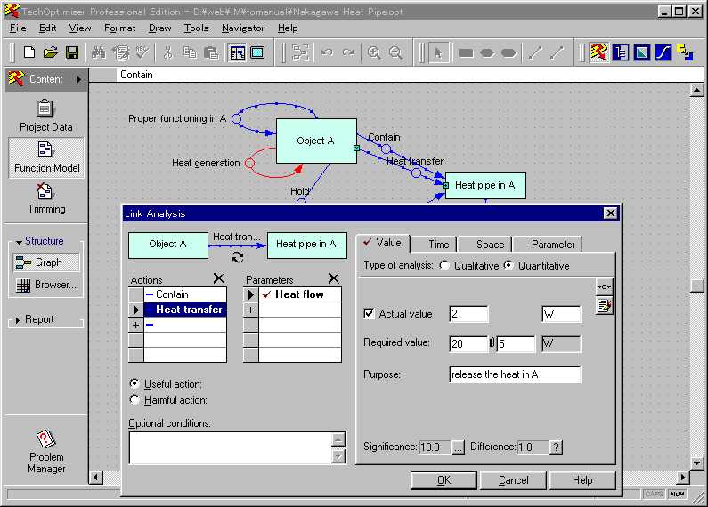
Fig. 8.3
[Link Analysis] window of [TechOptimizer Module]:
Specification of parameters of functions in function model
In the basic functional analysis,
you may specify the following items concerning the
functions (or actions) to clarify
the
problem in user's system:
Name of
function (or action)
Subject
and object components of the function
Specifying
whether the function is useful or harmful
Now a diagram is drawn, such as the
one shown in Fig. 8.2. Such a
diagram is useful to
represent and understand the functional
relationships among the system's components in a
conceptual way. It helps you
clarify your problems and focus your attention to solving
them. (It may be a practical
way of using this software that you draw a function model in
the simplest way in the [TechOptimizer
Module] and go ahead to use the three database
modules as described in Sections
2 to 7. )
9.
To functionally analyze the user's system
(TechOptimizer Module: Part 2. Functional Analysis)
In [TechOptimizer Module], you may
further refine the description of the function model
of your system and do the functional
analysis of your system, especially to find which
function can be improved most effectively.
9.1 Represent the function model with parameters
The basis of advanced functional
analysis can be formed by your input of appropriate
qualitative and quantitative parameters
to represent each function of the function model of
your system. For this purpose,
you may select and specify essential aspects among the
followings:
| [Parameters]: | Parameters to represent the function (multiple parameters are allowed to specify for one function) |
| qualitative or quantitative | distinction between qualitative/quantitative analyis |
| Parameter
values
(qualitative/quantitative): |
current value, desired value (specification
value) together with the allowance, objectives of the parameter, and
[Significance] (i.e. importance of achieving the specification) |
| Time dependence
of the parameter: |
simple graph representations of the time-dependent behavior of the current system and of the desired system |
| Spatial dependence
of the parameter; |
Simple graphs of representing the spatially dependent behavior of the current system and of the desired system |
| Dependence on
other parameters |
Among the parameter representations
mentioned above, the software tool [TechOptimizer
Module] utilizes the following two
values in its internal logic of functional analysis:
[Significance] of the parameter (user's
input value):
Specifies how important it is for the parameter of this function to satisfy
the desired
value for achieving the final objectives of the system; expressed qualitatively
in +/- 10
grades.
[Difference] of the parameter
(computed in the following expression by using user's
input values):
[Difference]
= ABS(desired value - current value)/(2* allowance)
In order to review the input parameters
of the functions, the display of [Function Model]
offers a [Browser] of the functions.
[Operation:
In the [Function Model] display, you may open the [Structure] menue at
the
left end and
then click the [Browser] button. In the [Browser] window thus opened,
you
may select
a number of ways of representation and functions by use of the tabs at
the
bottom. Figure
9.1 shows an example of the table of functions
which appear by clicking
the [Function
Table] tab. Among the columns in this table, the [Rank] and
[Performance]
columns are shown on gray background to indicate that these values are
computed by
the internal logic. ]
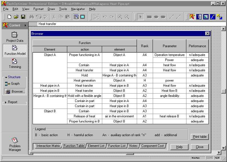
Fig. 9.1
An example of the [Browser] display of a functional model in [TechOptimizer
Module]:
An
example of the table of functions in the functional analysis
The functional analysis can further
be enhanced from the viewpoint of cost performance.
By clicking the [Component Cost]
tab at the bottom in the display as shown in Fig. 9.1,
you may input the costs of each
components of the system.
9.2 A list of localized problems
On the basis of the user's input
on the system, the software tool can display a full list of
localized, candidate problems to
be solved. Figure 9.2 demonstarates
an example of
[Problem Manager] window which is
opened by clicking the [Problem Manager] button
at the lower left in the main display
of [TechOptimizer Module]. There shows a list of
localized problems.
[Operation:
In the main display of the [TechOptimizer Module], you may click the
[ProblemManager]
button at the lower left end to open the [Problem Manager] window.
At the upper
left of the new window, a [List of Problems] are shown. By clicking
the
[weight balance]
button, you may rearrange the problems in the list in the order of the
computed importance
of problems. ]
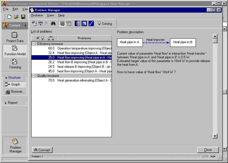
Fig. 9.2
An example of the [Problem Manager] window of [TechOptimizer Module]:
A list of localized problems otained by the functional analysis, with explanation
of one
of them
As shown in Fig.
9.2, when you select a problem in the list, its explanation appears
in
the [Problem description] window
at the right half of the display. It describes in sentence
"which parameter of which function
between what objects is to be improved" as a
problem. The sentences in
this window is preset in its structure, but by filling in several
pecies of user-input information
they make sence in a meaningful way. This technique is
quite admirable as unique capability
in [TechOptimizer Pro] (or in the TRIZ methodology
(?)).
The algorithm of computing the [Significance]
of the problems can be found in the on-
line help, which appears by clicking
the [Help] menue in the display in Fig. 9.2.
The
following information is used in
the algorithm:
[Difference]
of the parameter in question
[Significance]
of the parameter
Relative
[Importance] of the objective parameter(s) of the whole system
All these information are input by
the user, and are mostly quanlitative. Thus the
reliability of the [Significance]
of these localized problems output by the tool actually
depends on the user's input.
The more appropriately you input the relevant information,
the more meaningfully the tool can
localize your problem. In other words, the deeper
you understand your own problem,
the better the tool can support you. This is
reasonable because the role of this
sort of thinking-support software tool is to guide you
to think more appropriately.
9.3 Why should we localize the problem?
It is worthy to note here that the
user usually thinks he has one problem to solve and is
guided to input his system's structure
in the functional analysis in [TechOptimizer
Module]. The system, even
though the user writes in a simplified and abstract way, may
be composed of at least several
components and contain several or more-than-ten
functions and parameters.
[TechOptimizer Pro] (or the TRIZ methodology) lists up each
of these functions (or parameters)
as a "candidate problem" to be solved.
This is because the TRIZ methodology
recognizes that the essence of an invention is
achieved at a local point.
A technological innovation (or an invention) is born when a
localized ultimate task is achieved
by solving a severe contradiction. The birth of an
innovation at a small portion of
the system requires consequent improvements in other
parts of the system. This
is the TRIZ' way of understanding the technology innovation.
With this understanding, the three
problem-solving modules in [TechOptimizer Pro], i.e.
[Prediction Module], [Effects Module],
and [Principle Module], handle a localized
individual problem instead of the
whole body of problem of the system.
9.4 Management of
problem solving:
(Management by [Problem Manager])
[Operation: In the [Problem
Manager] display of Fig. 9.2, you may select
a [Problem] in
the [List of Problems] and click
any button of the three problem-solver modules at the
toolbar to initiate the problem
solver module. In such a case of initialization, a new
display appears as shown in Fig.
9.3 for an instance of the [Effects Module]. ]
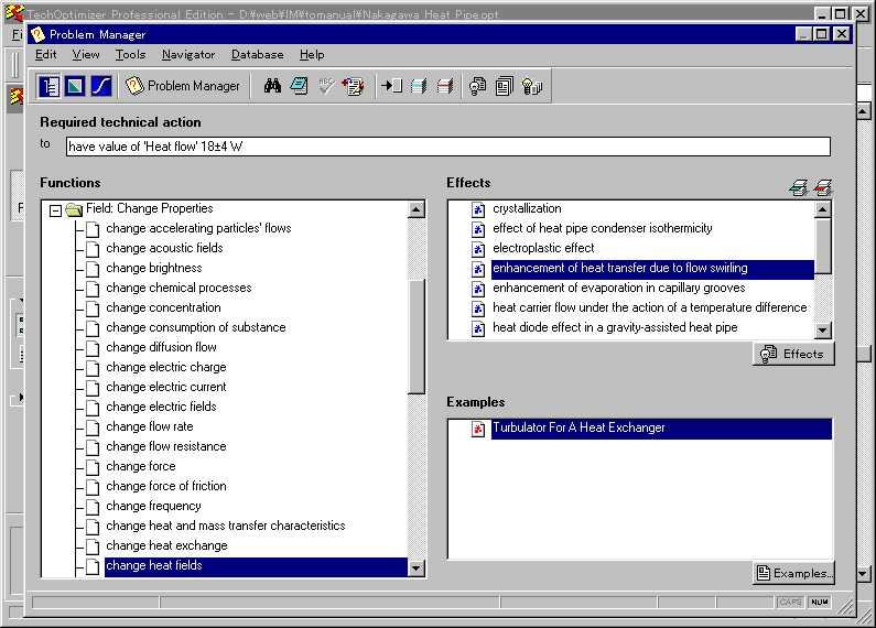
Fig. 9.3
An example of using the [Effects Module] under the control by the [Problem
Manager]
When one of the three problem solver
modules is called, the functions for problem
solving are the same as the case
when the module is called directly from the
[TechOptimizer Pro]; only difference
is that the processing in the former case is
controlled by the [Problem Manager].
As demonstrated in Fig. 9.3, the toolbar contains
the [Problem Manager] tools as well
as the tools of the problem solver, i.e. the [Effect
Module] in this case of example.
The problem specification previously input in Fig.
9.2
are shown automatically in the task
description window at the top of the display in Fig.
9.3.
After having tried various problem solving, you may click the [Problem
manager]
button in the toolbar of Fig.
9.3 and return to the display shown in Fig.
9.2.
10.
To examine the functional analysis of the user's system
(TechOptimizer Module: Part 3. Trimming; and Feature Transfer Module)
10.1 Trimming ([Trimming] in [TechOptimizer Module])
Another function of [TechOptimizer
module] is "Trimming". On the basis of the inputs
for the function model, this module
guides the user to eliminate a component of the user's
system and to try to figure out
an alternate system without problem. In the typical
training course given by the Invention
Machine Corporation, this function of trimming is
taught for a long time at the initial
stage; but the present author feels it too tedious. Users
who have been well trained in engineering
can think, on the basis of the function
modelling and functional analysis
as described in Sections 8 and 9, which component in
the system is extraneous or eliminable.
Then they will try to redraw alternative function
models having new system components.
10.2 Feature Trnasfer ([Feature Transfer Module])
The fifth module of the [TechOptimizer
Pro] is [Feature Transfer Module]. This module
implements one of the TRIZ techniques
called the "feature transfer". In contrast to the
current system, you are advised
to imagine first an ultimate ideal system disregarding its
feasibility. Especially, you
are advised to think of multiple ideal systems having
different merits and aspects.
They may certainly have disadvantages such as being
impossible to implement, not suitable
for the present situation, etc. Hence, you should
extract useful features from the
multiple ideal forms to compose a new system structure.
The present author has not mastered
this technique and this module; so he will not
describe them any further here.
Anyway, the present author understands that users
should better utilize the TRIZ methodology
and [TechOptimizer Pro] in the functions
previously described, before using
this [Feature Transfer Module].
| Top of this page | 8-1 Description of project | 8-2 Function model of user's system | 8-3 Function links | 9-1 Browsing function table | 9-2 Problem Manager | 9-3 Problem solving | Next page |
| Home Page | Software Tools | Papers and Tech. Reports | Top of this Tech. Report | Home Page |
Last updated
on Feb. 25, 1999. Access point: Editor:
nakagawa@utc.osaka-gu.ac.jp